<2. Connection>
2-2
IM 01C25T03-01E
2.3 Power Supply Voltage and
Load Resistance
Whenconguringtheloop,makesurethatthe
external load resistance is within the range in the
gurebelow.
(Note) With an intrinsically safe transmitter, external load
resistance includes safety barrier resistance.
600
250
0 10.5 16.6 25.2 42
External
load
resistance
R (Ω)
Power supply voltage E (V DC)
F0203.ai
Communication
applicable range
R=
E–10.5
0.0244
Figure 2.3 Relationship between Power Supply
Voltage and External Load Resistance
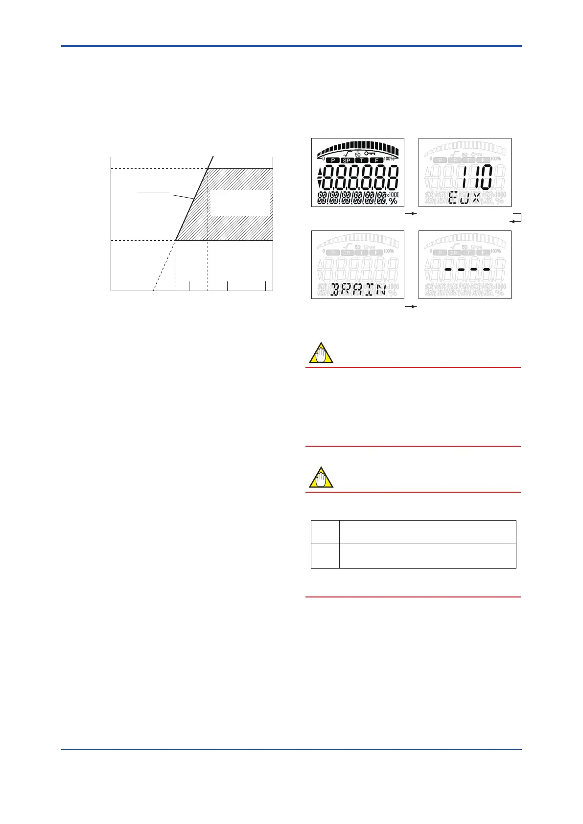
2.4 Integral Indicator Display
When Powering On
For models with the integral indicator code “D”, the
display shows all segments in the LCD and then
changes to the displays shown below sequentially.
All segments display Model name (3 s)
Communication Protocol (3 s)
– – – – (3 s)
F0200.ai
NOTE
For output signal code “D”, this function is
available for software revision 2.02 or later.
Software revision can be checked by the
parameter M15: SOFT REV.
Refer to section 3 “Operation” how to call up the
parameter.
NOTE
LCD display can be set to all segments display
only by the parameter I41: POWER ON INF.
ON
Show All segments display, Model name and
Communication Protocol when powering on.
OFF Show All segments display when powering on.
Refer to section 3 “Operation” how to call up the
parameter.
 Loading...


