<3. Operation>
3-14
IM 01C25T03-01E
(14) Range Change while Applying Actual
Inputs
(H10: AUTO P LRV, H11: AUTO P URV)
This feature allows the lower and upper range
values to be set up automatically with the actual
input applied. If the lower and upper range values
are set, C21: PRES LRV and C22: PRES URV are
changed at the same time.
Followtheprocedureinthegurebelow.
The measurement span is determined by the upper
and lower range values. Changing the lower range
value results in the upper range value changing
automatically, keeping the span constant.
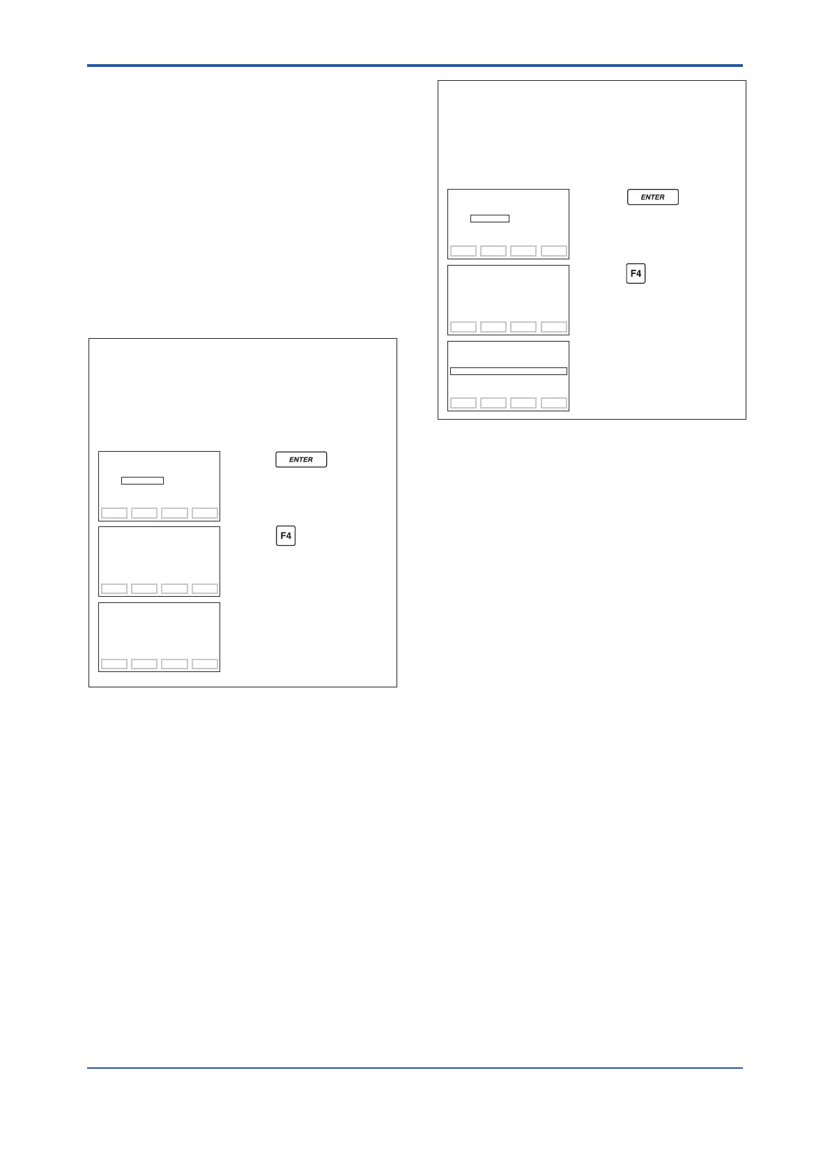
• Example 1: When changing the lower range
value to 0.5 kPa for the present
setting of 0 to 30 kPa, take the
following action with input pressure
of 0.5 kPa applied.
FEED NO OK
SET
H10:AUTO P LRV
0.5000 kPa
DATA DIAG PRNT ESC
PARAM
H10:AUTO P LRV
0.5000 kPa
H11:AUTO P URV
30.500 kPa
H20:AUTO SP LRV
0.0 MPa
ESC
SET
H10:AUTO P LRV
0 kPa
+ 0
F0334.ai
The upper range value is changed
keeping the span constant.
Parameters C21 and C22 are
changed at the same time.
Press the key twice.
The lower range value is changed
to 0.5 kPa.
Press the (OK) key.
Note that changing the upper range value does not
cause the lower range value to change but does
change the span.
• Example 2: When the upper range value is to
be changed to 10 kPa with the
present setting of 0 to 30 kPa, take
the following action with an input
pressure of 10 kPa applied.
FEED NO OK
SET
H11:AUTO URV
10.000 kPa
DATA DIAG PRNT ESC
PARAM
H10:AUTO P LRV
0 kPa
H11:AUTO P URV
10.000 kPa
H20:AUTO SP LRV
0.0 MPa
ESC
SET
H11:AUTO P URV
30 kPa
+ 30
The lower range value is not
changed, so the span changes.
Parameter C22 is changed at the
same time.
Press the key twice.
The upper range value is
changed to 10 kPa.
Press the (OK) key.
F0335.ai
(15) Sensor Trim
Each transmitter is factory characterized. Factory
characterization is the process of comparing a
known pressure input with the output of each
transmitter sensor module over the entire pressure
and temperature operating range. During the
characterization process, this comparison
information is stored in the transmitter EEPROM. In
operation, the transmitter uses this factory-stored
curve to produce a process variable output (PV), in
engineering units, dependent on the pressure input.
The sensor trim procedure allows you to adjust
for local conditions, changing how the transmitter
calculates process variables. There are two ways
to trim the sensor: a zero trim and a full sensor trim.
A zero trim is a one-point adjustment typically used
tocompensateformountingpositioneectsor
zero shifts caused by static pressure. A full sensor
trim is a two-point process, in which two accurate
end-point pressures are applied (equal to or greater
than the range values), and all output is linearized
between them.
 Loading...


