<3. Operation>
3-8
IM 01C25T03-01E
(3) Damping Time Constant Setup
(C30: AMP DAMPING)
When the instrument is shipped, the damping time
constant is set at 2.00 seconds unless otherwise
speciedintheorder.Followtheprocedurebelow
to change the damping time constant.
Note that setting the quick response parameter
(D50: QUICK RESP) ON enables you to set the
damping time constant between 0.00 to 0.49
second.
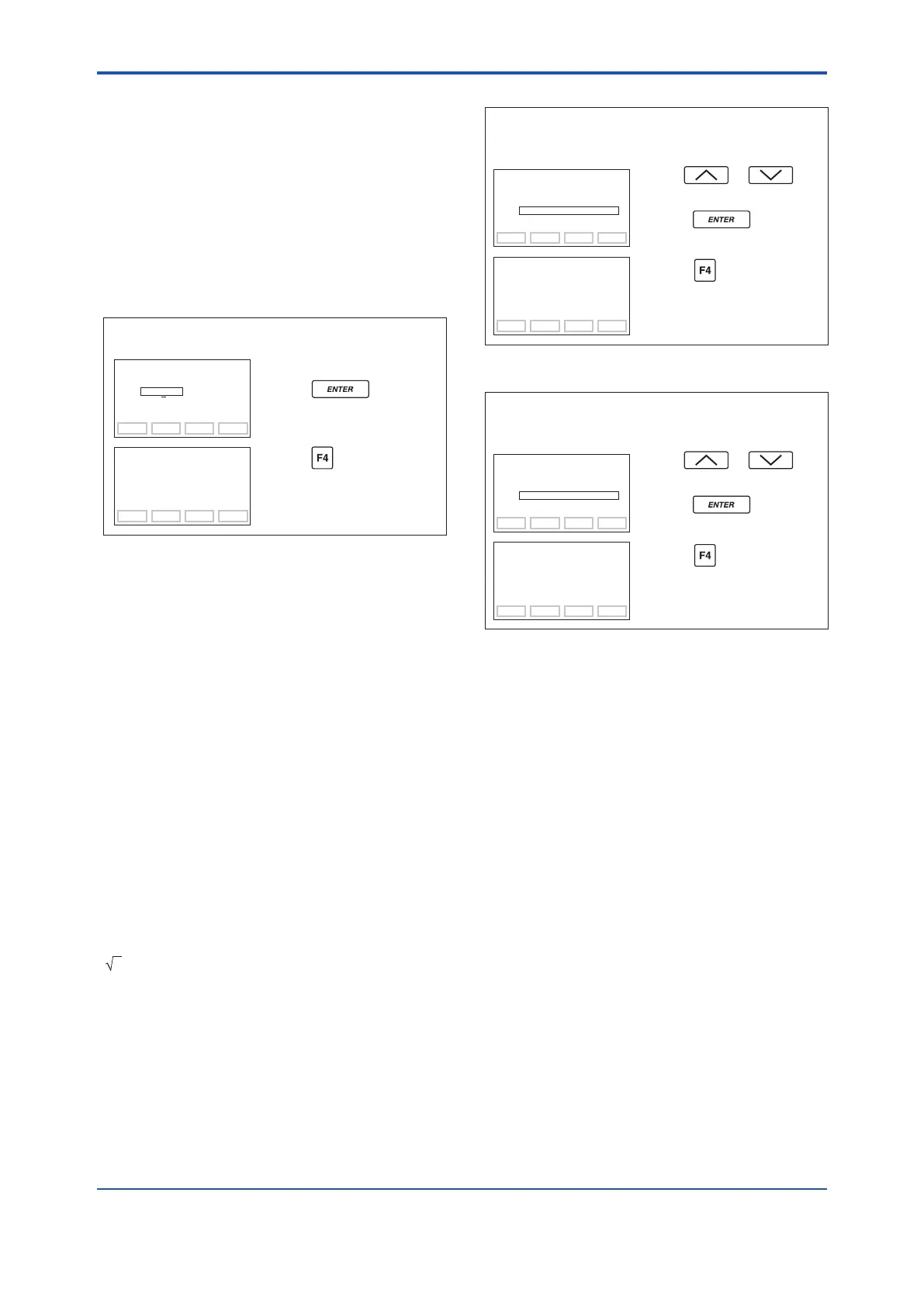
• Example: Change from 2.00 to 4.00 seconds.
ESCCLR
SET
C30:AMP DAMPING
4.00 sec
FEED NO OK
SET
C30:AMP DAMPING
2.00 sec
+ 004.00
Enter 4.
Press the key twice to
enter the setting.
F0315.ai
Press the (OK) key.
Note 1: The damping time constant set here is the time
constantfortheamplierassembly.Thedampingtime
constant for the entire transmitter is the sum of the
valuesfortheamplierassemblyandforthecapsule
assembly.
Note 2: When the damping time constant is set to less than
0.5 second, communication may occasionally be
unavailble during the operation, especially while output
changes dynamically.
(4) Output Mode and Integral Indicator
Display Mode Setup
(C40: OUTPUT MODE, I20: P DISP
MODE)
The mode setting for the output signal and the
integral indicator can be performed independently.
Thismodeissetasspeciedintheorderwhenthe
instrument is shipped. Follow the procedure below
to change the mode.
If the instrument is equipped with an integral
indicator and the display mode is SQUARE ROOT,
“ ” is displayed on the integral indicator.
• Output mode for 4-20 mA output
• Example: Set output mode from Linear to
Square root.
ESC
SET
C40:OUTPUT MODE
SQUARE ROOT
FEED NO OK
SET
C40:OUTPUT MODE
LINEAR
< LINEAR >
< SQUARE ROOT >
Use the or key
to select SQUARE ROOT.
Press the key twice to
enter the setting.
Press the (OK) key.
F0316.ai
• Integral indicator display mode
• Example: Set display mode from Linear to
Square root.
ESC
SET
I20:P DISP MODE
SQUARE ROOT
FEED NO OK
SET
I20:P DISP MODE
LINEAR
< LINEAR >
< SQUARE ROOT >
Use the or key
to select SQUARE ROOT.
Press the key twice to
enter the setting.
Press the (OK) key.
F0317.ai
(5) Output Signal Low Cut Mode Setup
(D10: LOW CUT, D11: LOW CUT MODE)
Low cut mode can be used to stabilize the output
signal near the zero point. The low cut point can
be set in a range from 0 to 20%, the direct ratio
corresponding to the output signal of 4 to 20 mA.
(Hysteresis: ±10% of the cut point)
Either LINEAR or ZERO can be selected as the low
cutmode.Unlessotherwisespecied,thecutmode
is set to LINEAR at the factory.
Note that when the output modes of the output
signal and the integral indicator are selected as
SQUARE ROOT and LINEAR accordingly, the low
cut function is not available for the integral indicator
display.
 Loading...


