<2. Handling Cautions>
7
IM 01C22A01-01E
• Intrinsically Safe for Class I, Division 1, Groups A,
B, C & D. Class II, Division 1, Groups E, F & G and
Class III, Division 1 Hazardous Locations.
• Nonincendive for Class I, Division 2, Groups A, B, C &
D. Class II, Division 2, Groups E, F & G and Class III,
Division 1 Hazardous Locations.
• Outdoor hazardous locations, NEMA 4X.
• Temperature Class: T4
• Ambient temperature: –40 to 60°C
Note 2. Entity Parameters
• Intrinsically Safe Apparatus Parameters
[Groups A, B, C, D, E, F and G]
Vmax = 30 V, Ci = 22.5 nF, Imax = 165 mA,
Li = 730 μH, Pmax = 0.9 W
* Associated Apparatus Parameters
(FM approved barriers)
Voc ≤ 30 V, Ca > 22.5 nF, Isc ≤ 165 mA, La > 730 μH,
Pmax ≤ 0.9W
• Intrinsically Safe Apparatus Parameters
[Groups C, D, E, F and G]
Vmax = 30 V, Ci = 22.5 nF, Imax = 225 mA,
Li = 730 μH, Pmax = 0.9 W
* Associated Apparatus Parameters
(FM approved barriers)
Voc ≤ 30 V, Ca > 22.5 nF, Isc ≤ 225 mA,
La > 730 μH, Pmax ≤ 0.9 W
• Entity Installation Requirements
Vmax ≥ Voc or Vt, Imax ≥ Isc or It,
Pmax (IS Apparatus) ≥ Pmax (Barrier),
Ca ≥ Ci + Ccable, La ≥ Li + Lcable
Note 3. Installation
• Barrier must be installed in an enclosure that meets
the requirements of ANSI/ISA S82.01.
• Control equipment connected to barrier must not use
or generate more than 250 V rms or V dc.
• Installation should be in accordance with ANSI/ISA
RP12.6 “Installation of Intrinsically Safe Systems for
Hazardous (Classifi ed) Locations” and the National
Electric Code (ANSI/NFPA 70).
• The confi guration of associated apparatus must be
FMRC Approved.
• Dust-tight conduit seal must be used when installed in
a Class II, III, Group E, F and G environments.
• Associated apparatus manufacturer’s installation
drawing must be followed when installing this
apparatus.
• The maximum power delivered from the barrier must
not exceed 0.9 W.
• Note a warning label worded “SUBSTITUTION OF
COMPONENTS MAY IMPAIR INTRINSIC SAFETY,”
and “INSTALL IN ACCORDANCE WITH DOC. No.
IFM012-A12 P.1 and 2.”
Note 4. Maintenance and Repair
• The instrument modifi cation or parts replacement by
other than authorized representative of Yokogawa
Electric Corporation is prohibited and will void Factory
Mutual Intrinsically safe and Nonincendive Approval.
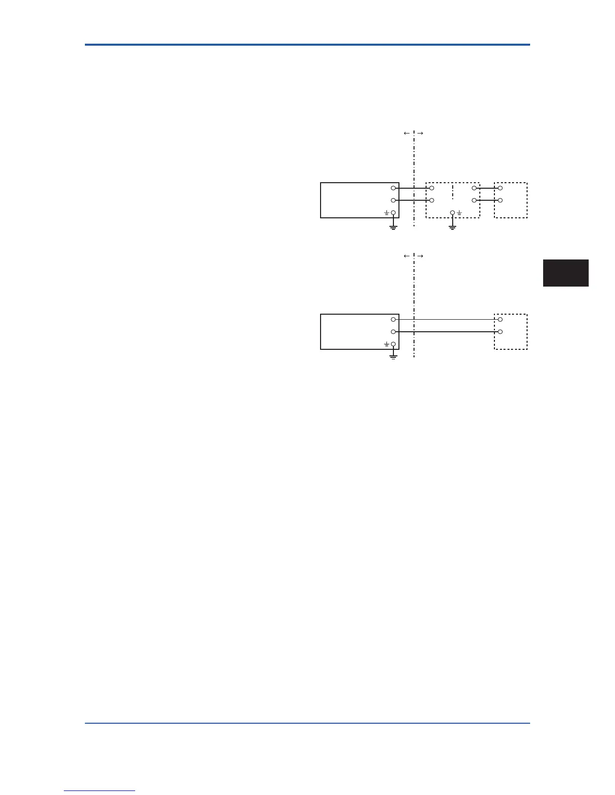
F0204.ai
Class I, II, III, Division 1,
Groups A, B, C, D, E, F, G
EJA Series Pressure
Transmitters
EJA Series Pressure
Transmitters
Safety Barrier
Supply
Supply
Hazardous Location Non-hazardous Location
Hazardous Location Non-hazardous Location
General
Purpose
Equipment
+
–
+
–
+
–
+
–
+
–
+
–
[Intrinsically Safe]
Class I, II, Division 2,
Groups A, B, C, D, E, F, G
Class III, Division 1.
Not Use
Safety Barrier
[Nonincendive]
General
Purpose
Equipment
b. FM Explosionproof Type
Caution for FM explosionproof type.
Note 1. Model EJA Series differential, gauge, and
absolute pressure transmitters with optional
code /FF1 are applicable for use in hazardous
locations.
• Applicable Standard: FM3600, FM3615, FM3810,
ANSI/NEMA250
• Explosionproof for Class I, Division 1, Groups B, C
and D.
• Dust-ignitionproof for Class II/III, Division 1, Groups E,
F and G.
• Outdoor hazardous locations, NEMA 4X.
• Temperature Class: T6
• Ambient Temperature: –40 to 60°C
• Supply Voltage: 42 V dc max.
• Output signal: 4 to 20 mA
Note 2. Wiring
• All wiring shall comply with National Electrical Code
ANSI/NEPA70 and Local Electrical Codes.
• When installed in Division 1, “FACTORY SEALED,
CONDUIT SEAL NOT REQUIRED.”
Handling Cautions
2