<2. Wiring and Installation>
10
IM 12A01A02-12E 9th Edition : Mar. 23, 2018-00
CAUTION
Do not tighten up four front panel screws one by one.
Eachfrontpanelscrewshouldbetightenedupintwotimesofscrewing.And,rstlythescrew
at the upper left should be screwed a bit, the next is at the lower right, third is at the upper right,
and fourth is at the lower left. The second round is the same sequence again to tighten up four
screws.
Do not use an electric screwdriver with high revolutions. If an electric screwdriver is used for
these front panel screws, the revolutions of the electric screwdriver should be less than 400 rpm.
Four screws should be tightened to the following torque; 0.8 to 0.9 N•m
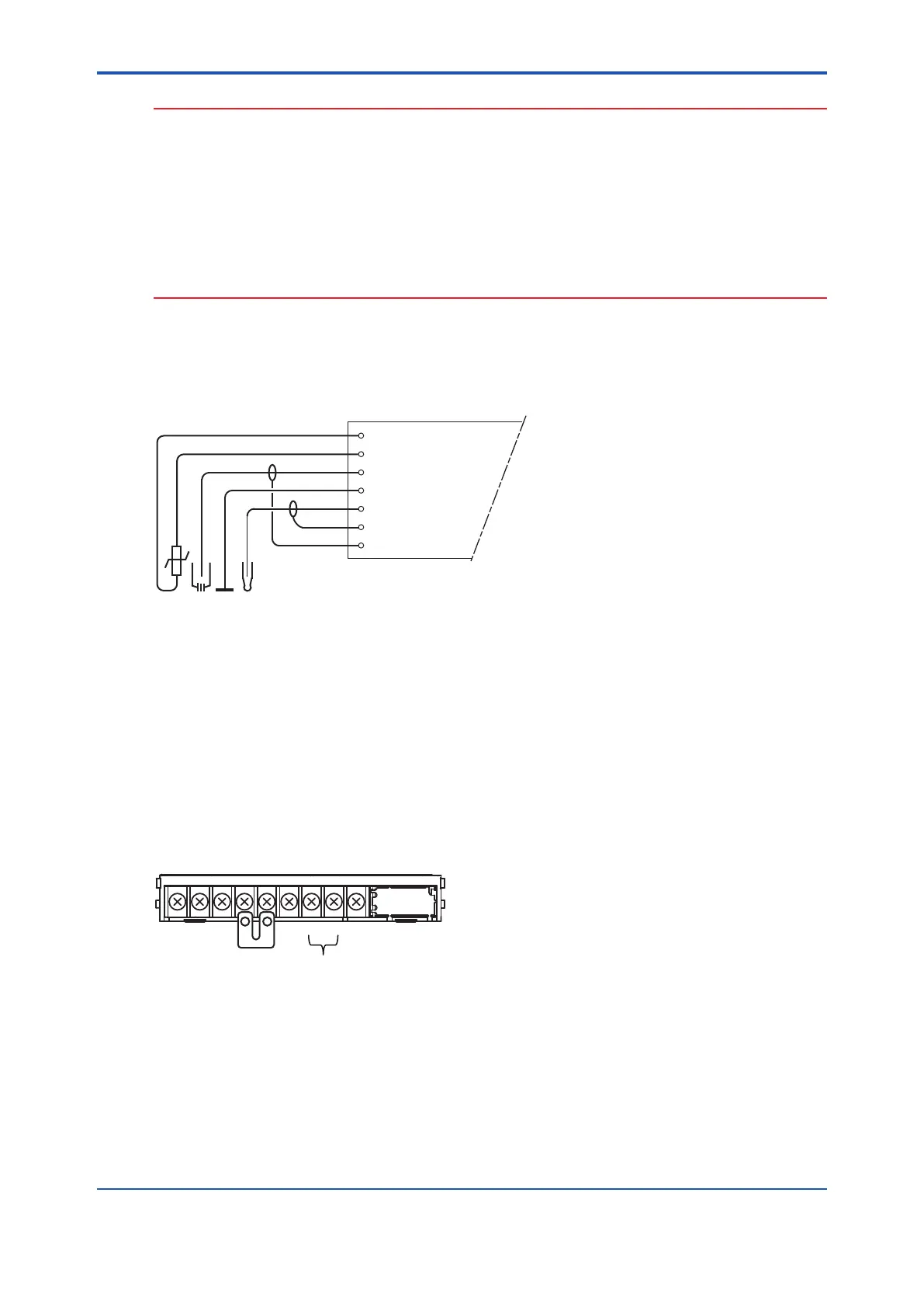
2.3.1 pH Measurement
Conventional pH sensors are connected to the module as follows:
11 Temperature
12 Temperature
13 Reference
14 Solution ground
15 Glass (measure)
16 Shield
17 Shield
FLXA202/FLXA21
REFTC PHLiquid
Earth
In addition to the wiring of the sensor, insure that a jumper for low-impedance sensor inputs is
installed. The jumpers can be found on the plastic sensor module cover and can be stored in the
lower level module wiring cover.
• pH Glass Electrode is a high impedance sensor input
• Standard reference electrodes and an ORP/REDOX electrode are low impedance sensor
inputs
• Special electrodes using 2 glass sensor (example: Pfaudler, SC24V) do not need jumpers.
Terminals15-19areidentiedasinput1(HighImpedance)andterminals13-18aredenedas
input 2 (Low Impedance). For conventional pH sensors, the jumper is placed as illustrated:
16
15191713181412
11
PH
Input 1
Input 2
Glass sensor on Input 1.
Reference sensor on Input 2.

 Loading...


