<2. Wiring and Installation>
13
IM 12A01A02-12E 9th Edition : Mar. 23, 2018-00
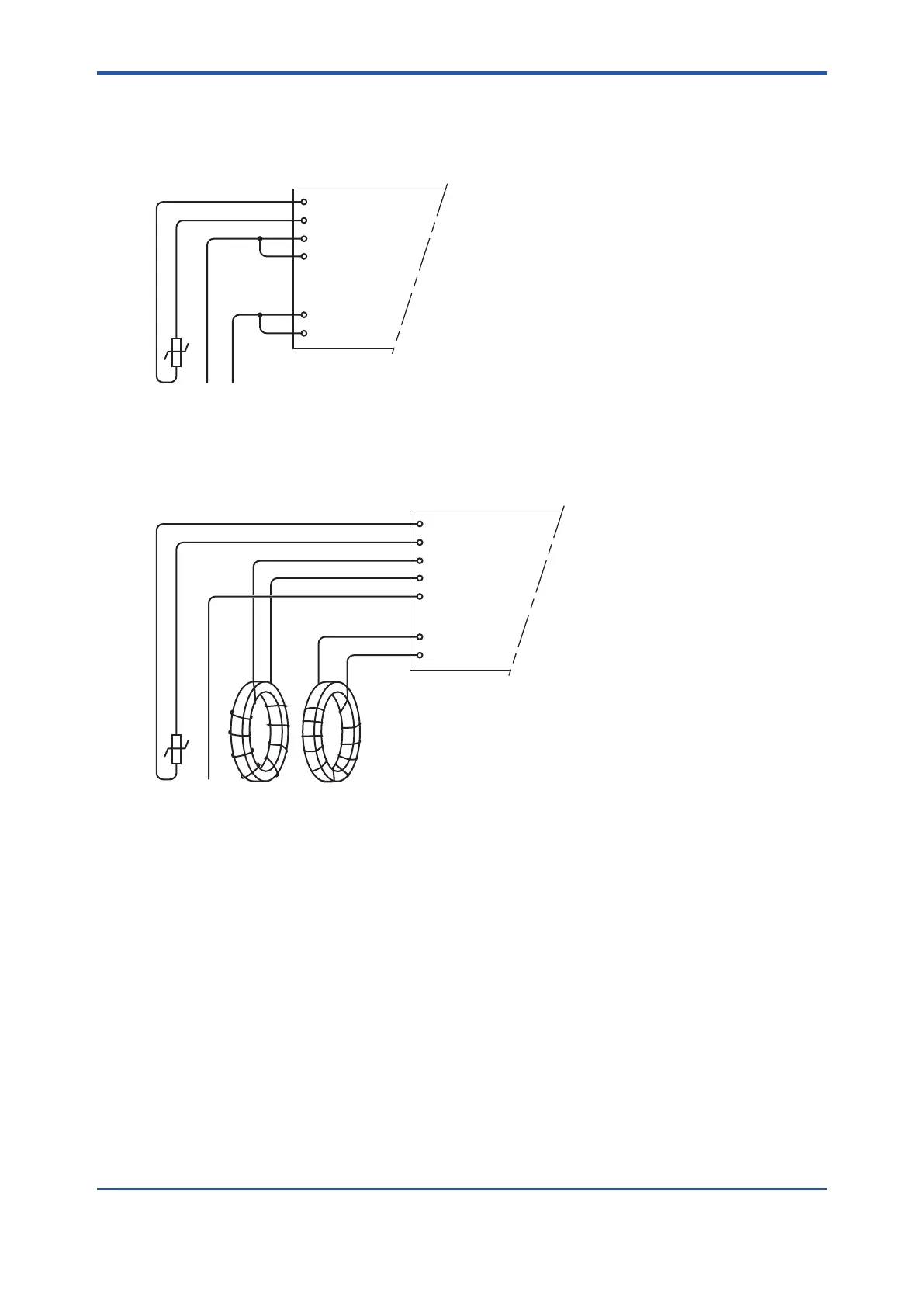
The above diagram shows wiring for 4-electrode conductivity sensors, such as SC42-SP34
large bore series. For 2-electrode conductivity sensors, such as SC42-SP36 small bore series,
jumpers must be installed between terminals 13-14 and between terminals 15-16, as shown in
the diagram below.
11 +
-
V-
i-
Temp
V+
i+
12
13
14
15
16
FLXA202/FLXA21
2.3.4 ISC Measurement
ISC40 sensors are connected to the module as follows:
11 +
-
Temp
Receive coil
Drive coil
12
13
17
15
16
14
shield
Sensor shield
(internal)
shield
FLXA202/FLXA21
The sensors are supplied with integral cables and each individual wire is marked with the
corresponding terminal numbers.
2.3.5 DO Measurement
TheinputmoduleforDOmeasurementissuitablefordierenttypesofDOsensors:
i. Galvanic sensors like model DO30G
ii. Polarographic sensors like HAMILTON’S Oxyferm and Oxygold
The connection is as follows:

 Loading...


