<2. Wiring and Installation>
5
IM 12A01A02-12E 9th Edition : Mar. 23, 2018-00
2.2.1 Cables, terminals and glands for FOUNDATION
Fieldbus or PROFIBUS PA
Wire and install the system by referring to chapter 2 in the FLXA21 instruction manual (IM
12A01A02-01E).
The FOUNDATION Fieldbus or PROFIBUS PA power supply is 9 to 32 V DC. The wiring is the
same.
However, for the FOUNDATION Fieldbus or PROFIBUS PA cables, see Table 2.1.
Table 2.1 FOUNDATION Fieldbus or PROFIBUS PA Cables and transmissible Length
Parameters Conditions Type A Type B Type C Type D
MaxDCResistance,Ω/km per conductor 22 56 132 20
Max Attenuation, dB/km 1.25 f, (39 kHz) 3.0 5.0 8.0 8.0
Gauge —
#18 AWG
(0.82 mm
2
)
#22 AWG
(0.32 mm
2
)
#26 AWG
(0.13 mm
2
)
#16 AWG
(1.25 mm
2
)
Max Length, meters — 1,900 1,200 400 200
Note: 1900 m is trunk + sum of Spurs (Max length type A cable)
Yokogawa recommends the use of Type A.
Usage of Type B and D is restricted.
Yokogawa does not recommend the use of Type C.
Table 2.2 Recommended length of Spur Cables
Number of spur cables
Length of a non-intrinsically
safe spur cable
15-16 60 m
13-14 90 m
1-12 120 m
Note: • 1 device per spur.
• Keep as short as possible (min 1 m)
250
600
1000
0
24.718
V - 11.5
0.022
R =
1295
1617 22.8
4040
Voltage (V)
2-sensor measurement
Digital Communication
Range (HART)
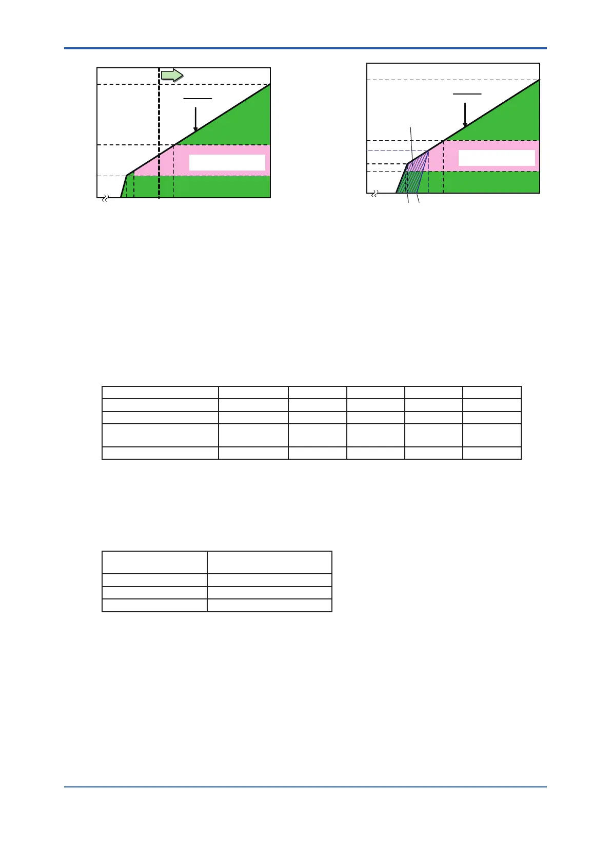
Figure 2.1 Supply Voltage and Load Resistance
for pH/ORP (analog sensor), SC and DO
250
304
600
516
1000
0
24.7
18
V - 11.5
0.022
R =
1295
17
40
22.86
40
Except SENCOM
Voltage (V)
Digital Communication
Range (HART)
18.2
21
Figure 2.2 Supply Voltage and Load Resistance
for ISC and pH/ORP SENCOM sensor

 Loading...


