<2. Wiring and Installation>
6
IM 12A01A02-12E 9th Edition : Mar. 23, 2018-00
l When using a SENCOM module
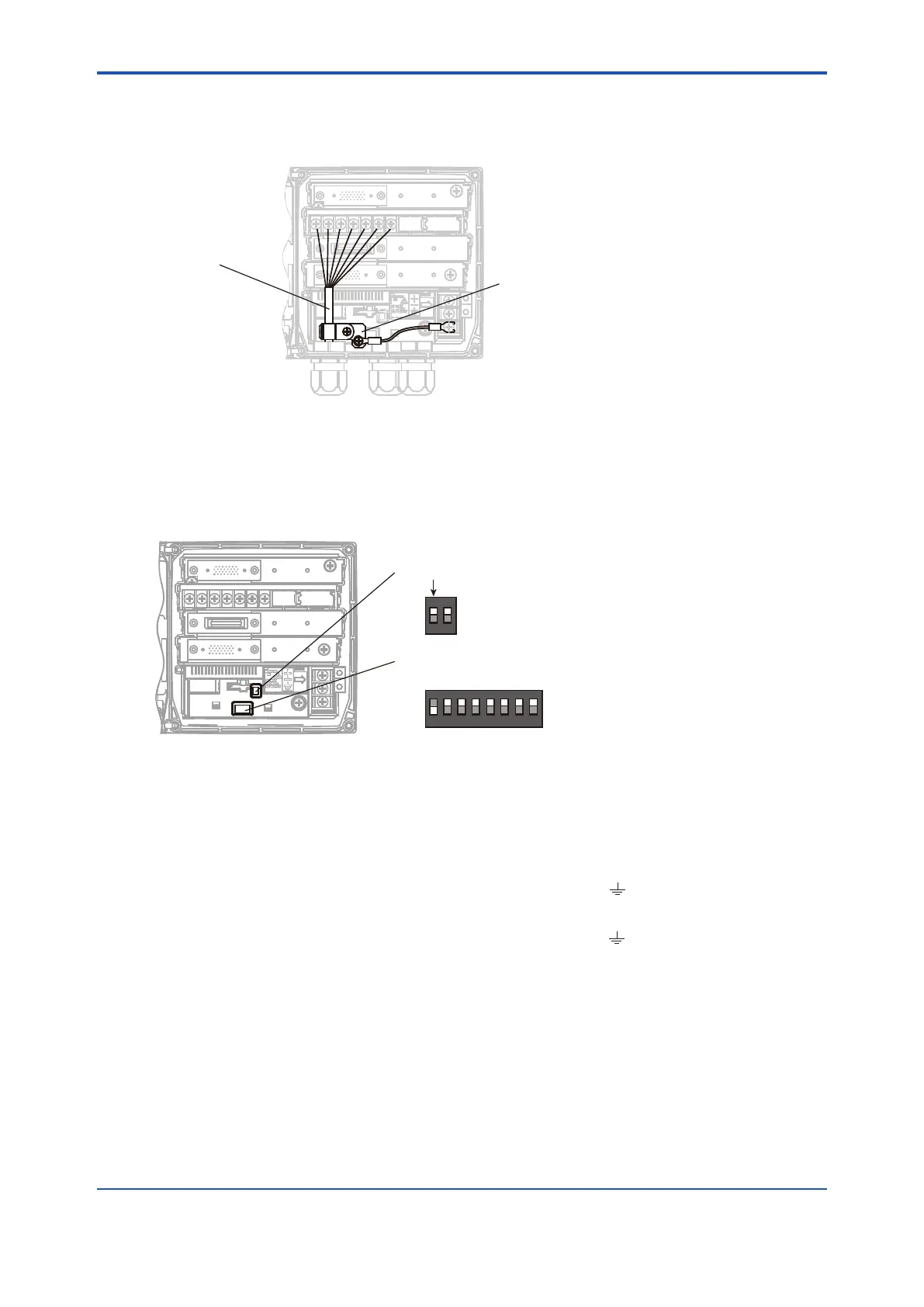
WhenusingaSENCOMmodule,youneedtousethesuppliedcableclamptoxthesensor
cables in place. Attach the supplied cable clamp as shown in Figure 2.3.
Sensor cable
Cable cramp
Figure 2.3 When using a SENCOM module
l DIP switches
Figure 2.4 shows the DIP switches for setting the address and write protection.
Normally, you do not have the change them from the default settings.
Write protection switch (Default: OFF)
Address switch
(Default: Hardware address is disabled)
ON
OFF
1: Write protect
2: Simulate (only for FOUNDATION Fieldbus)
1
ON
OFF
2
1 2
3 4 5 6 7 8
7
Address bit
6 5 4 3 2 1 0
Figure 2.4 DIP switches
2.2.2 Grounding
ThewayofconnectingthegroundingisdierentfromFLXA202,FLXA21.
• FLXA202
The ground cable is connected to the outer terminal marked
• FLXA21
The ground cable is connected to the inner terminal marked

 Loading...


