Do you have a question about the YOKOGAWA PH402G and is the answer not in the manual?
Procedure for inspecting the instrument upon delivery to ensure it is undamaged and correct.
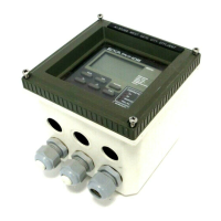
Describes the intended uses of the EXA converter in industrial monitoring and control applications.
Details input specifications, ranges, transmission signals, temperature compensation, and communication.
Covers performance metrics, environmental limits, housing, data protection, and regulatory compliance.
Provides a table for understanding model, suffix, and option codes for configuration.
Guidelines for selecting an installation site and mounting methods, including diagrams.
Steps to open the instrument and prepare for wiring connections, including safety precautions.
Instructions for connecting AC or DC power supplies, including precautions and fuse ratings.
Guidance on wiring the unit's four contact outputs for alarm or control functions.
Procedures for connecting analog output signals (0-20 mA or 4-20 mA) to peripherals.
Information on connecting various sensor types and setting impedance measurement jumpers.
Detailed wiring diagrams for different sensor types and connection cables, including color coding.
Instructions for mounting a stainless steel tag plate for identification purposes.
Overview of the EXA operator interface, including access levels and key functions.
Detailed explanation of the function of each key on the EXA operator interface.
Procedure for setting passcode protection for different operating levels.
Examples illustrating button presses and screen sequences during operation.
Explains how to access and interpret various display functions for pH, ORP, and rH.
Illustrates the display flow for pH measurement and related functions.
Illustrates the display flow for ORP measurement and related functions.
Illustrates the display flow for rH measurement and related functions.
Standard operation using maintenance mode for parameter setup.
Steps to set up the EXA for peak performance in custom applications.
Guidance and detailed explanations for using service codes for advanced configuration.
Step-by-step guide for performing automatic calibration using buffer tables.
Method for manual adjustment of asymmetry potential or 2-point calibration.
Routine for calibrating using a representative process sample.
Entering calibration data directly via service codes.
Detailed procedures for various calibration methods.
Detailed screen flow for performing an automatic calibration.
Performing automatic calibration while keeping the HOLD function active.
Guide for manual calibration, including 2-point adjustment.
Steps for manual calibration of the zero point.
Steps for manual calibration of the ORP offset (Asymmetry potential).
Procedure for calibrating using a process sample with lab analysis.
Routine cleaning and component replacement for the converter unit.
General advice on sensor cleaning, electrolyte replenishment, and recalibration frequency.
Overview of self-diagnostics, electrode checks, and error signaling.
Checks performed after calibration for asymmetry potential and slope.
System for checking sensor impedance over a wide range for diagnostics.
A list of available spare parts with their corresponding part numbers.
A table summarizing default and user-configurable settings for various functions.
Checklist to verify configuration settings against standard and optional parameters.
General information on sensor compatibility and programmable inputs.
Guidance on setting up contact outputs, current outputs, wash cleaning, and communications.
Steps for setting up impedance measurement, temperature sensor, and calibration for Pfaudler sensors.
Summary of software changes and updates for the PH402.
Definition of pH as a logarithmic measure of Hydrogen ion activity.
Definition of Oxidation-Reduction Potential as a measure of oxidizing/reducing power.
Definition of rH as a composite value indicating oxidizing power with compensation.
Difference between isothermal point of intersection and the zero point.
Sensitivity of pH electrode, expressed as mV/pH percentage.
Isothermal point of intersection, where temperature response is null.
pH value where the electrode combination yields 0 mV output.
Error code E0 for buffer solution temperature outside range 0-50°C.
Error code E1 for measurement stabilization failure during calibration.
Error code E2 for asymmetry potential exceeding set limits.
Error code E3 for slope sensitivity falling outside specified limits.
Error code E4.1 for low impedance on input 1, indicating potential breakage.
Error code E4.2 for low impedance on input 2, indicating potential breakage.
Error code E5.1 for high impedance on input 1, indicating disconnection or pollution.
Error code E5.2 for high impedance on input 2, indicating disconnection or pollution.
Error code E10 indicating a failure to write data to EEPROM.
Error code E11 related to wash response time or recovery time issues.
Error code E12 for ORP or rH values exceeding preset limits.
Error code E14 indicating missing or invalid calibration data.
Error code E20 indicating that all programmed data has been lost.
Error code E23 for zeropoint falling outside specified limits.
| Model | PH402G |
|---|---|
| Interface | Not applicable |
| Data Rate | Not applicable |
| Power Supply | Not applicable |
| Operating Pressure | 0 to 1 MPa |
| Reference Electrode | Ag/AgCl |
| Body Material | PPS 40GF |