Installation and wiring 3-13
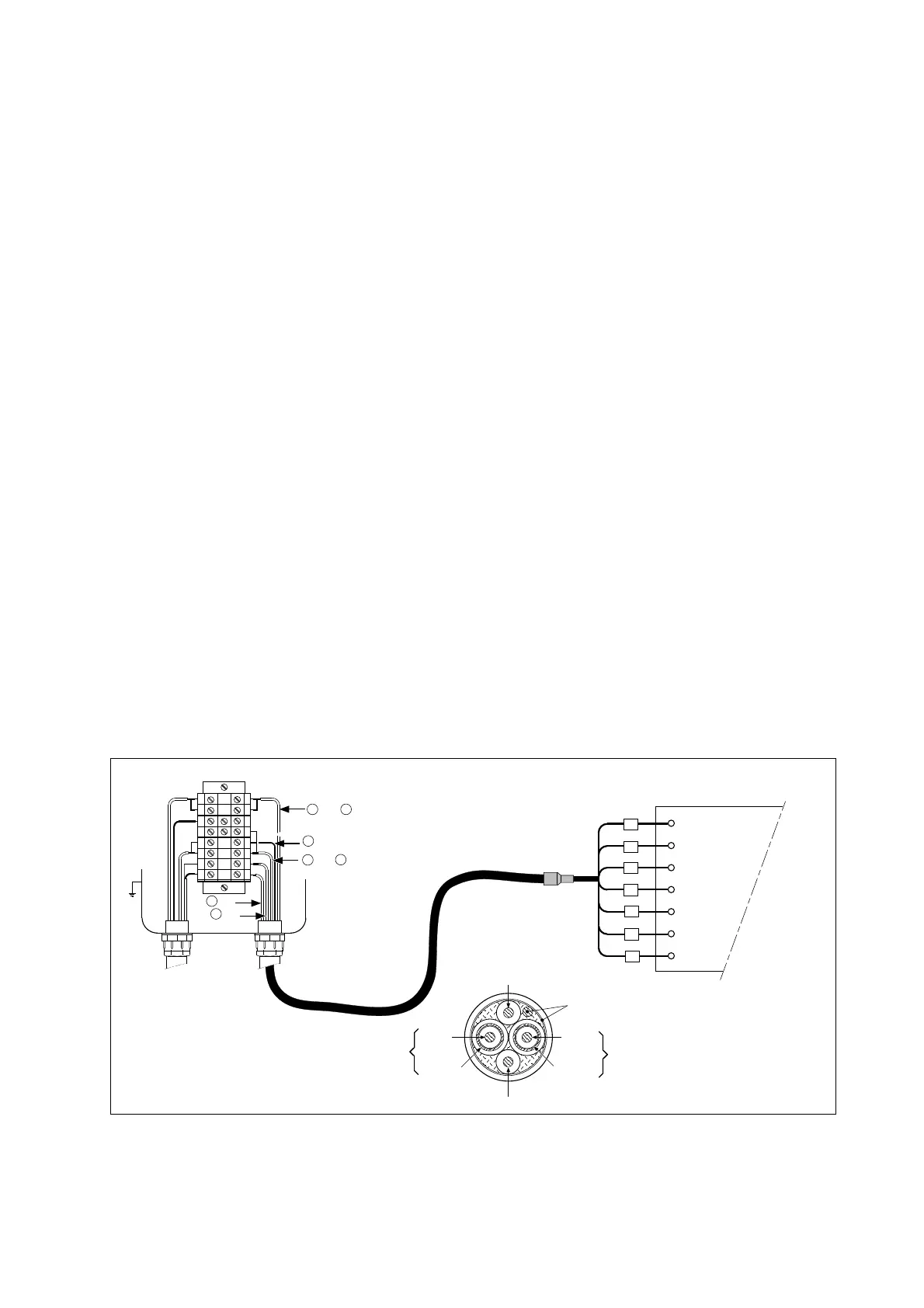
Refer to figure 3-12 to assemble the grommet connections:
1. First remove the nut and standard rubber seal from the selected gland
2. Discard the seal. This will be replaced later by the special grommet
3. Thread the cables through the nut and the gland
4. Connect the cables to their designated terminals
5. Arrange the cables to avoid tangles and insert the grommet between the gland and the nut
6. The grommet is split to permit the cables to be mounted after connection. (This also ensures even length
adjustment.)
7. Ensure that any unused holes are filled with the blanking pieces
8. Tighten the nut to form a firm seal. (Hand-tight is sufficient.)
NOTE:
The special gland is intended to be used to seal the multiple cables from the Yokogawa flow fittings such as
FF20 and FP20. The designated cables are WU20 sensor cables, which are approximately 5 mm (0.2 “) in
diameter, and 82895002 liquid earth cables, which are approximately 2.5 mm (0.1 “) in diameter.
For sensor systems using a single cable, like the FU20 (FU25) and the PR20, PD20, PF20 and PS20, the
standard gland will accommodate the cable adequately. Single cables between approximately 7 mm and 12
mm (0.28 “ and 0.47 “) can be sealed properly with these glands.
3-7-3. Sensor cable connections using junction box (BA10) and extension cable (WF10)
Where a convenient installation is not possible using the standard cables between sensors and converter, a
junction box and extension cable may be used. The Yokogawa BA10 junction box and the WF10 extension
cable should be used. These items are manufactured to a very high standard and are necessary to ensure
that the specifications of the system can be met. The total cable length should not exceed 50 metres (e.g.
5 m fixed cable and 45 m extension cable). In the case of systems using dual high impedance sensors (e.g.
Pfaudler 18), then the cable length is restricted to 20 metres (fixed cable only, no extension with WF10).
IM 12B6B3-E-H
 Loading...

