IM 12B6B3-E-H
Installation and wiring 3-5
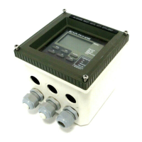
Figure 3-7. Input and output connections
3-3-3. AC power
Connect terminal 1 to the phase line of the AC power and terminal 2 to the zero line. Terminal 3 is for the
power ground. This is separated from input ground by a galvanic isolation.
3-3-4. DC power
Connect terminal 1 to the positive outlet and terminal 2 to the negative outlet. Terminal 3 is for the power
ground. This is separated from input ground by a galvanic isolation. A 2-core screened cable should be
used with the screen connected to terminal 3. The size of conductors should be at least 1.25 mm
2
. The
overall cable diameter should be between 7 & 12 mm.
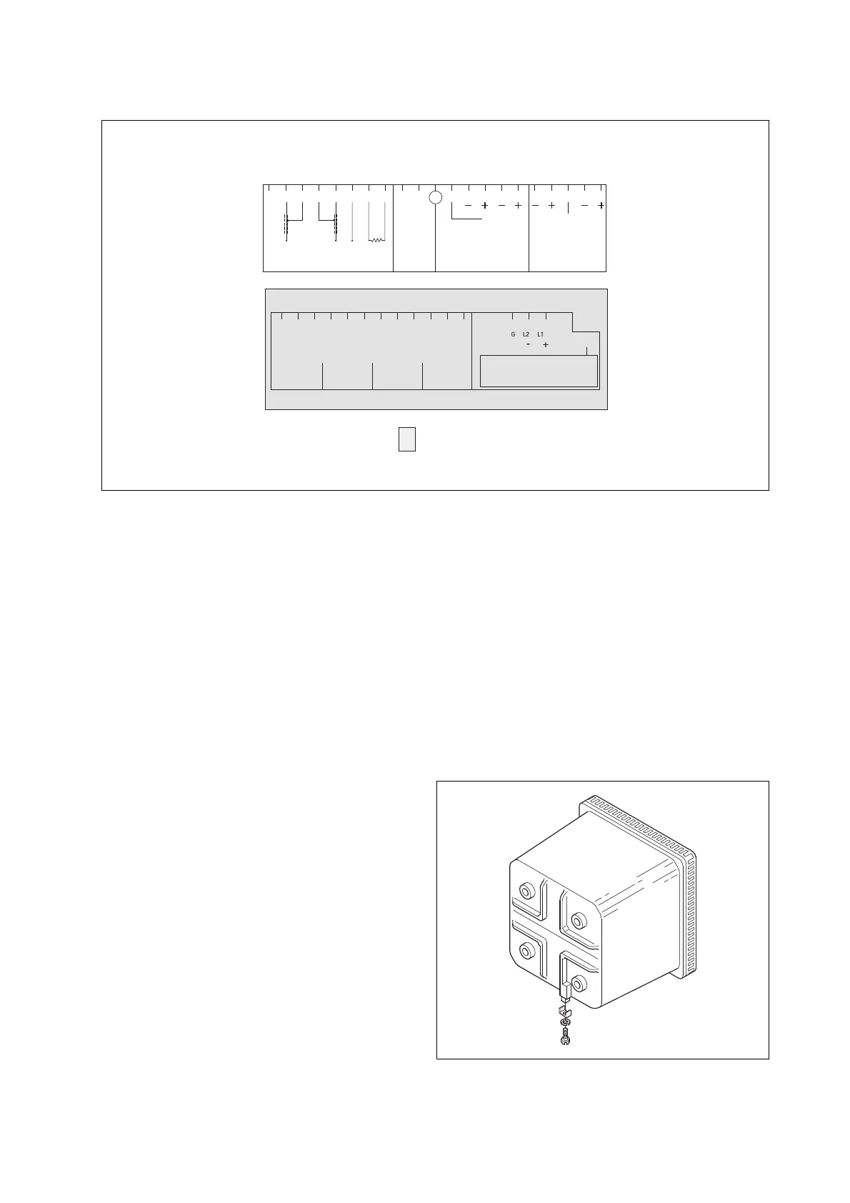
3-3-5. Grounding the housing
To protect the instrument against interference, the housing should be connected to ground by a large area
conductor. This cable can be fixed to the rear of the housing using a braided wire cable. See figure 3-8.
3-3-6. Switching on the instrument
After all connections are made and checked, the
power can be switched on from the power supply.
Make sure the LCD display comes on. All segments
will illuminate, then the instrument will momentarily
display its unique serial number. After a brief interval,
the display will change to the measured value. If
errors are displayed or a valid measured value is not
shown, consult the troubleshooting section (Chapter
8) before calling Yokogawa.
Figure 3-8. Grounding the housing
ref.
temp.
sens.
 Loading...

