IM 12B6B3-E-H
Spare parts 9-1
9. SPARE PARTS
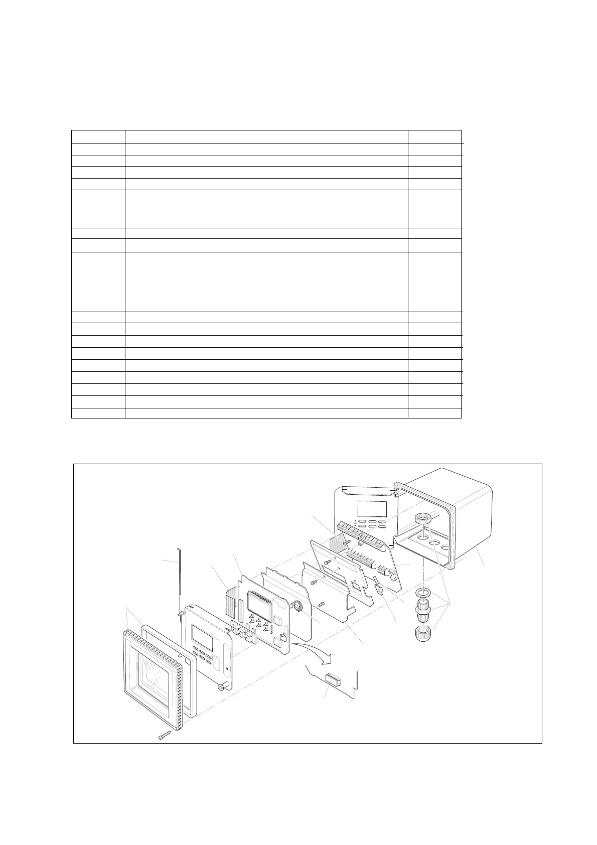
Table 9-1. Itemized parts list
Item No. Description Part no.
1 Cover assembly including gasket and 4 fixing screws (M4 x 20) K1541JG
2 * Digital / display board K1543DB
3 EPROM (programmed memory chip) K1543BK
4 Protective cover for power terminal complete with fixing screw K1541JH
5 * Input and power board (230 VAC) K1543PE
Input and power board (115 VAC) K1543PG
Input and power board (24 VDC) K1543PL
6 Fuse holder K1543AA
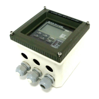
7 EXA 402 case K1541JJ
8 Fuse (box of 10 pieces) for 230 V AC (250 V AC, 50 mA, T) K1543AK
Fuse (box of 10 pieces) for 115 V AC (250 V AC, 100 mA, T) K1543AL
Fuse (box of 10 pieces) for 24 V DC (250 V AC, 1 A, T) K1543AM
Fuse (box of 10 pieces) for 100 V AC (250 V AC, 100 mA, T) K1543AL
9 Cable gland set (one gland including seal and backing nut) K1500AU
10 Flat cable K1543AB
11 Securing screw set K1543AC
12 Hingepin K1543KS
13 Lithium cell (battery) K1543AJ
14 RS485/232 Converter for communication to PC K1543WM
Options
/U Pipe and wall mounting hardware K1542KW
/PM Panel mounting hardware K1541KR
/SCT Stainless steel tag plate K1543ST
* NOTE: Contact your nearest Yokogawa service centre for the procedure for changing items 2 and 5.
(Re-initialisation of the instrument).
 Loading...

