IM 12B6B3-E-H
3-4 Installation and wiring
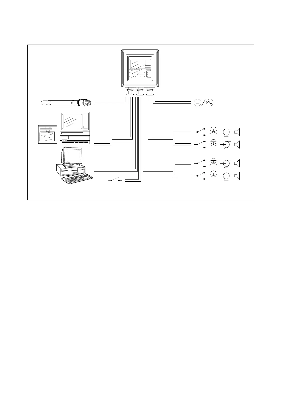
Figure 3-6. System configuration
3-3. Wiring the power supply
3-3-1. General precautions
Make sure the power supply is switched off. Also, make sure that the power supply is correct for the speci-
fications of the EXA and that the supply agrees with the voltage specified on the textplate. Remove the front
cover by unscrewing the four screws to check this textplate on the top of the display board.
Local health and safety regulations may require an external circuit breaker to be installed. The instrument is
protected internally by a fuse. The fuse rating is dependent on the supply to the instrument. The 250 VAC
fuses should be of the “time-lag” type, conforming to IEC127.
Fuse ratings are 230 VAC - 50 mA; 100 VAC - 100 mA; 115 VAC - 100 mA; 24 VDC - 1.0 A.
The internal fuse is located next to the power terminals (in the lower righthand corner).
3-3-2. Access to terminal and cable entry
Terminals 1, 2 and 3 on the bottom terminal strip are used for the power supply. Guide the power cables
through the gland closest to the power supply terminals. The terminals will accept wires of 2.5 mm
2
(14
AWG). Use cable finishings if possible.
Connect the wires as indicated in the wiring diagram (refer to figure 3-6).

 Loading...

