2. Transportation, Storage and Installation
2-10
TI 32P01J10-01EN
Size of Cabling Holes in Floor
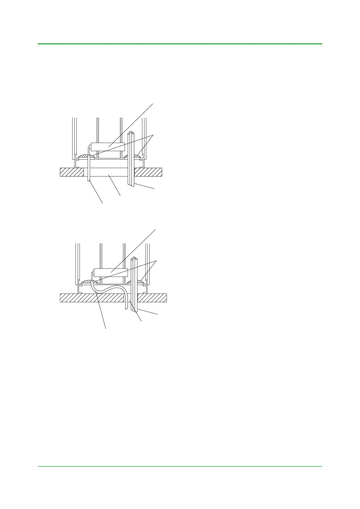
For ease of cabling, and for separating power cables from signal cables, it is recommended
that you make holes in the oor for cabling that are the maximum size indicated in the oor
plans. If the specied maximum size hole cannot be provided due to the oor construction or
pit dimensions, the size may be smaller within the range indicated in the plans. If you use the
specied minimum size of hole, use exible cables that can bend inside the channel base.
Cabinet
Cabling to front
Cabling hole
Cabling to rear
board
Figure Cabling through Maximum Size Hole
Cabinet
Sealed with putty
Cabling to front
Cabling hole
Cabling to rear
board
Figure Cabling through Minimum Size Hole
Nov. 27, 2015-01
 Loading...