1. System Installation Requirements
1-12
TI 32P01J10-01EN
1.3 Power Supply System
The following conditions should be met:
• Voltage and frequency uctuations are within the limits specied for each system
component.
• Waveform distortion is within limits.
• High-frequency noise is not at a level that aects system operation.
• Use an UPS (uninterruptible power supply) if necessary.
AC Power Specication
AC power used for the system must be within the specied rated voltage and the peak value
must be greater than the minimum specied (see below). DC power must be within 24 V DC
-10%/+20% at the power supply terminals.
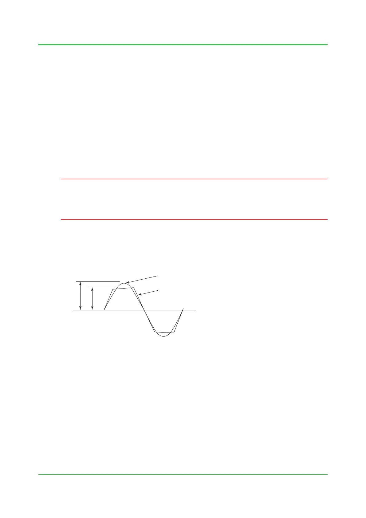
IMPORTANT
If the power unit has high output impedance or high wiring impedance, the resulting voltage drop
attens the input voltage wave, forming a distorted waveform with a low peak value (“B” in the
chart below).
Even if the eective value of the distorted input voltage wave is the same as that specied for a
non-distorted input voltage wave, the voltage across the terminals of the smoothing capacitor
in the power circuit may be so low that the system detects power failure. Even if input voltage
waves A and B shown below have the same eective value of 100 V AC, wave B will have a
lower smoothing capacitor terminal voltage.
Peak B
F010301.ai
A: Ideal, non-distorted input voltage wave
B: Distorted input voltage wave
Figure Distorted Input Voltage Waveform
Oct. 25, 2016-00
 Loading...