2. Transportation, Storage and Installation
2-19
TI 32P01J10-01EN
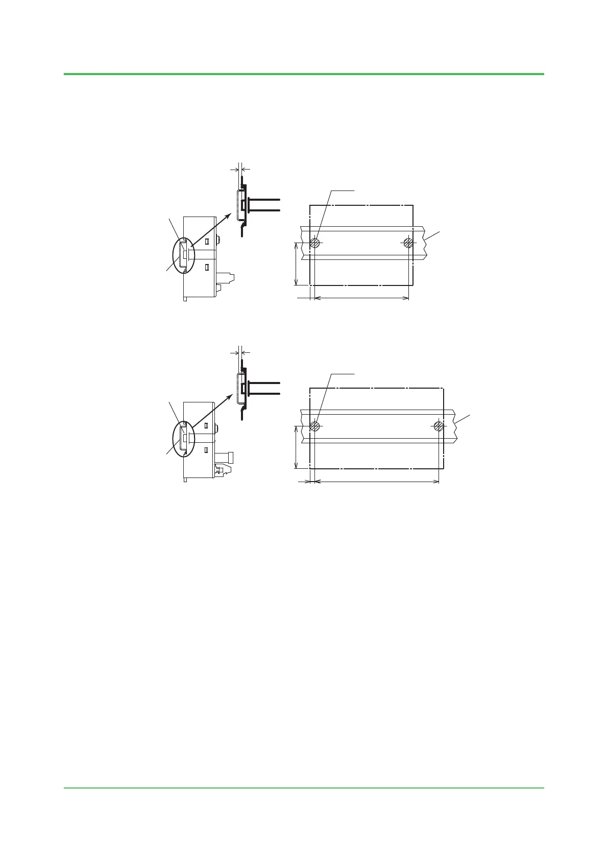
Remarks for Installating to a DIN Rail
On the back of DIN rail mountable terminal board, there are two bumps (projections) for xing
screws on the wall. Be sure not to let mechanical interference happen between these bumps
and screw tops from the DIN rail. The height of the shaded areas in the below gures must be
kept as 2.5 mm or shorter than the DIN rail surface.
F020512E.ai
Terminal board outline
Unit: mm
2.5 mm max
2 - Ø10
Bumps (projections)
Terminal board side view
DIN rail
DIN rail
100 ± 0.5
5
45
Figure Mounting SBA4D to DIN rail for terminal board
F020513E.ai
140 ± 0.5
5
Terminal board outline
Unit: mm
2.5 mm max
2 - Ø10
Bumps (projections)
Terminal board side view
DIN rail
DIN rail
45
Figure Mounting A2BM4, SBD2D, SBD3D, and SBD4D to DIN rail for terminal board
Cautions of the Power Source for the Loads of SBM54D
In the case of using multiple power sources for the loads of SBM54D, there are cautions of the
load voltage.
When the load voltage is dierent between loads.
All of the load voltages must be in either the range below.
• Load voltages ≤ 100 V
• 50 V < Load voltages ≤ 150 V
Cautions of the Digital Output Module when SBM54D is Used
The functions of disconnection diagnosis, ON pulse diagnosis and OFF pulse diagnosis for
SDV541 must be disabled when SBM54D is used.
Oct. 5, 2018-00
 Loading...