2. Transportation, Storage and Installation
2-22
TI 32P01J10-01EN
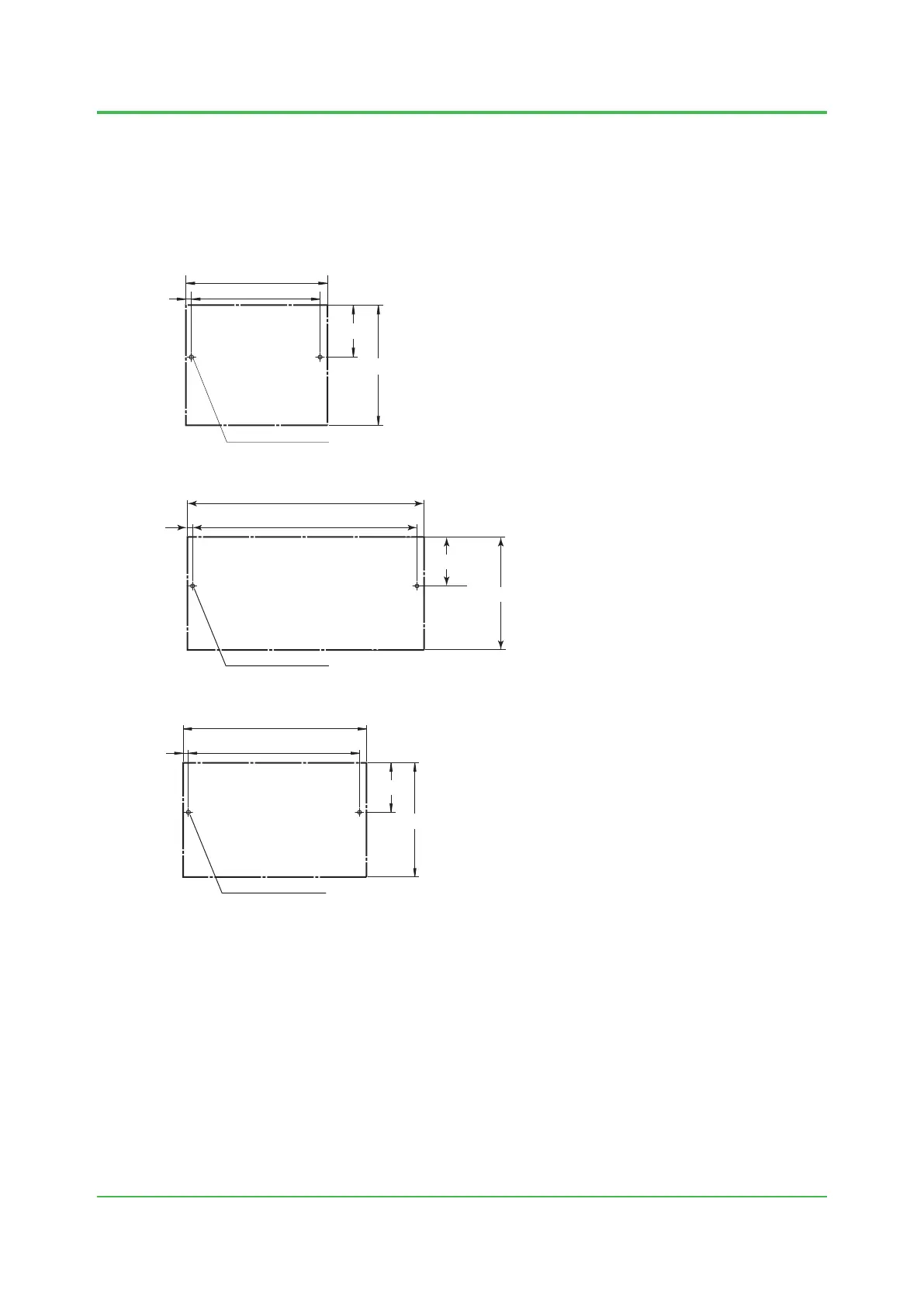
Remarks for Mounting on a Wall Surface
The following gure shows the screw installation dimensions for a wall mountable terminal board.
Installation screws for the terminal board are not supplied and should be purchased separately.
You need two installation screws. If you are using binding heads, use M4 screws with a length of
at least 10 mm. If you are using screws with washers, use M4 screws with a length of at least 12
mm. The screw tightening torque is approximately 0.8 N·m.
Unit: mm
100
±0.5
2-M4 screw holes
110
(40.5)
(93.5)
Device Mounting Area
5
F020516E.ai
Figure Screw Installation Dimensions for the A2BM4, SBA4D, SBT4D, and SBR4D
200
±0.5
210
(40.5)
(93.5)
5
Device Mounting Area
2-M4 screw holes
Unit: mm
Figure Screw Installation Dimensions for the S1BB4D
140
±0.5
150
(40.5)
(93.5)
5
F020517E.ai
Device Mounting Area
2-M4 screw holes
Unit: mm
Figure Screw Installation Dimensions for the SBD2D, SBD3D, and SBD4D
Grounding
Ground the equipment at a single point using the functional ground terminal provided on the base
plate.
Installation Direction
Mount the device to the wall with the screws in the vertically correct direction. Check the
installation direction in General Specications (GS).
Oct. 5, 2018-00
 Loading...