2. Transportation, Storage and Installation
2-25
TI 32P01J10-01EN
Installation Conditions
· Applicable units
Safety Control Unit S2SC70-F/SSC60-F: 1 unit
Safety Node Unit SNB10D and Unit for Optical ESB Bus Repeater Module SNT10D:
Up to 13 units
Primary Power Supply Bus Unit AEP7D and AEPV7D: Up to 2 units
Other heat-generating devices must not be installed in the cabinet.
· Fan conguration
There are the following two types of fan congurations.
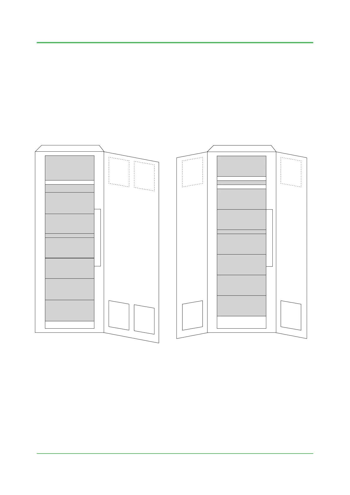
Type 1: Conguration of door fans, node fans, and door vents
Type 2: Conguration of door fans, node fans, and roof vent
Node 1
(S2SC70-F)
Node 2
Fan(S2SC70-F)
Space for 1U
Node 3
Node fan 1
Node 4
Node 5
Node 6
Node 7
42
41
40
39
38
37
36
35
34
33
32
31
30
29
28
27
26
25
24
23
22
21
20
19
18
17
16
15
14
13
12
11
10
9
8
7
6
5
4
3
2
1
A
E
P
V
7
D
Door fan
Door fan
Front
Node 8
Space for 1U
Node 9
Node fan 2
Space for 1U
Node 10
Node fan 3
Node 11
Node 12
Node 13
Node 14
42
41
40
39
38
37
36
35
34
33
32
31
30
29
28
27
26
25
24
23
22
21
20
19
18
17
16
15
14
13
12
11
10
9
8
7
6
5
4
3
2
1
A
E
P
V
7
D
Door fan
F020520.ai
Door fan
Rear
Space for 2U
Space for 3U
Door vent
Door vent
Door vent
Door vent
Example of a Single Door on the Front Example of Double Doors on the Rear
Figure Fan Conguration of Type 1 and Installation Positions in the Cabinet
Oct. 25, 2016-00
 Loading...