Sensor installation
General Instruction Manual
Installation
IM 01U10B00-00EN-R, 3rd edition, 2018-07-09
31 / 90
6.3.4 Installation recommendation for viscosity measurements
For the Rotamass sensor this function can only be used if it is present an external differ-
ential pressure transmitter (to order separately) measuring the pressure difference at the
flow line. The accuracy of the estimated viscosity is strongly depending on the accuracy
of the pressure transmitter and the correct position and implementation of the pressure
taps.
NOTICE
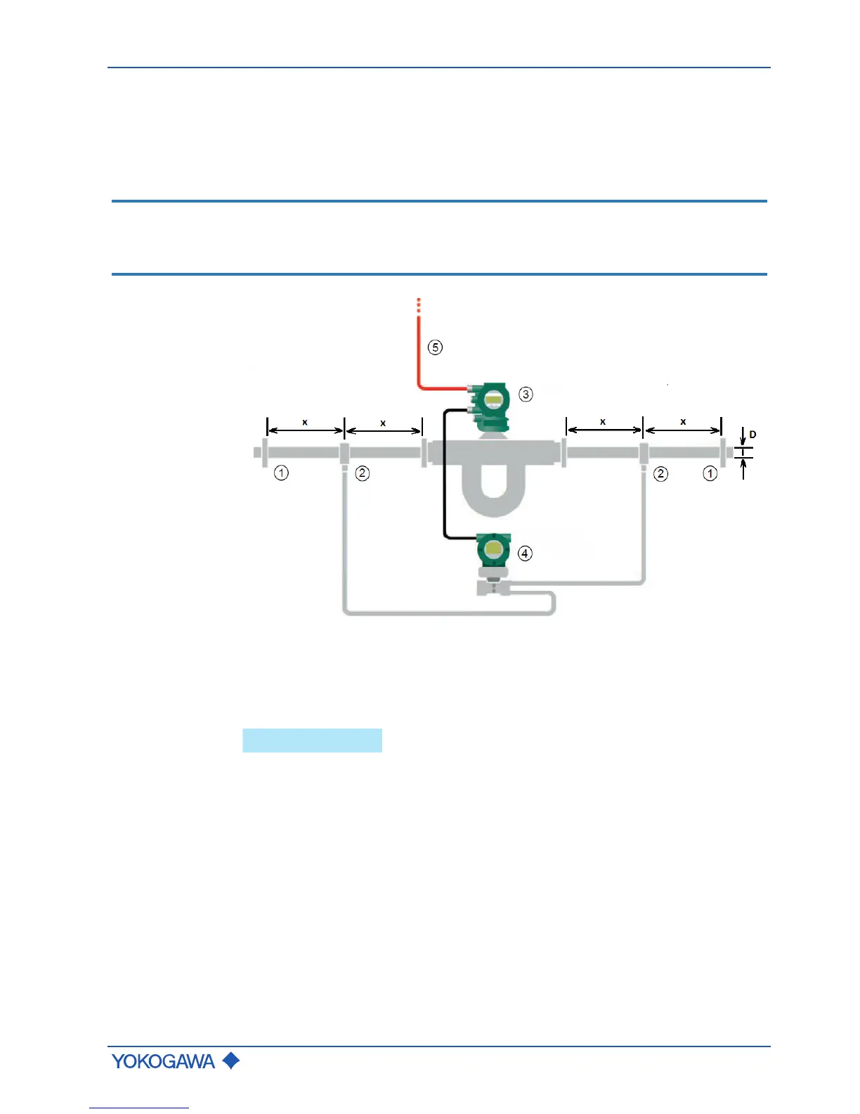
The needed pressure taps have to be placed at the flow line at approximately 4D … 5D
upstream and downstream of the Rotamass sensor. The differential pressure transmitter
is directly connected via analog input to the Rotamass transmitter (analog input function
must be available).
Fig.25: Positioning of pressure taps
① Mounting flanges ④ Differential pressure transmitter
② Pressure taps ⑤ HART communication
③ Rotamass Total Insight
x Flow line upstream or downstream of the Rotamass Total Insight sensor
D Inner diameter of process line
 Loading...


