General Instruction Manual
Wiring
Transmitter
52 / 90
IM 01U10B00-00EN-R, 3rd edition, 2018-07-09
7.4.2 HART communication
For devices with HART communication, the HART interface, along with the analog signal,
is available at the output Iout1. A load resistance of 230 – 600Ω at Iout1 is recom-
mended.
How to connect to the communication tools is described in the applicable Software In-
struction Manual.
7.4.3 MODBUS communication
Modbus
interface
Modbus interface of Rotamass Total Insight is implemented in accordance with "MOD-
BUS over serial line specification and implementation guide V1.02", for details of instru-
mentation see website of the Modbus organization (http://www.modbus.org/).
Modbus
connections
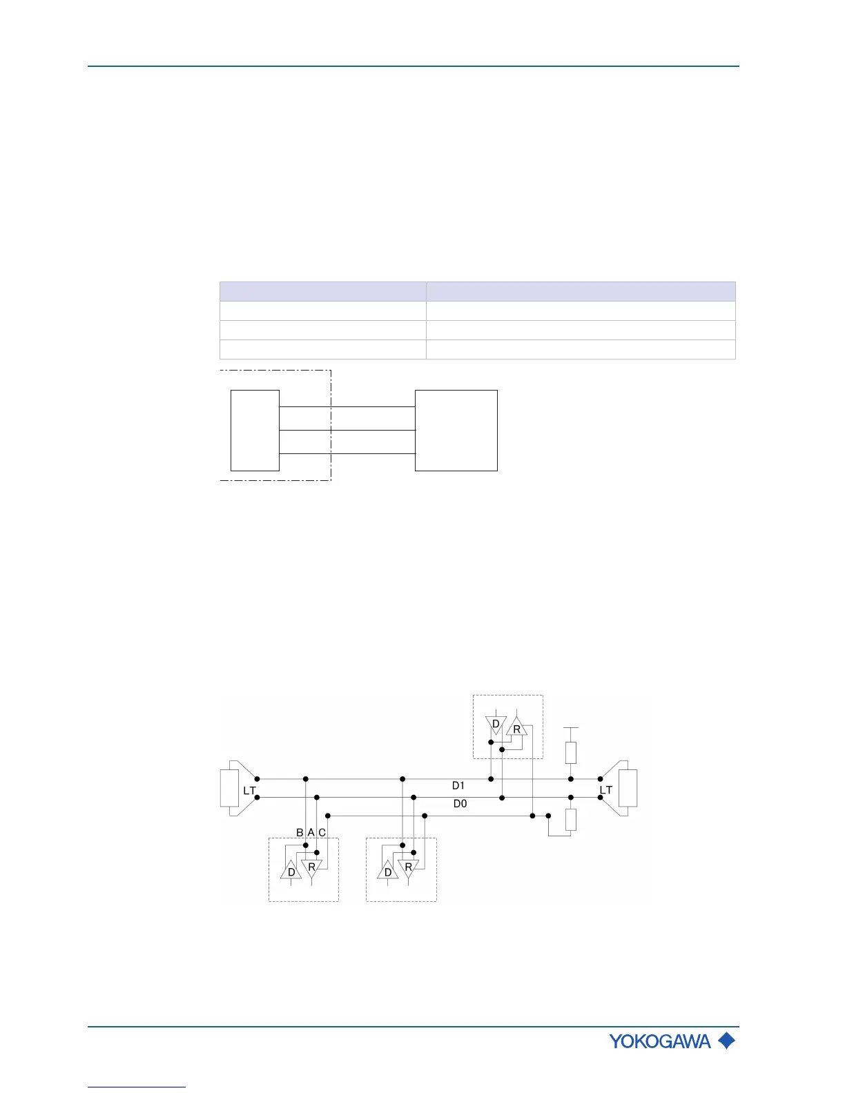
Terminal Description
I/O3 - Modbus C (Common)
I/O4 + Modbus B (D1)
I/O4 - Modbus A (D0)
Fig.36: MODBUS communication
Modbus cable
3-Wire cable (twisted pair (D0, D1) and Common) with shield should be used. Wire gauge
should be AWG24 or wider.
Rotamass Total Insight has a RS485 electrical interface, operating in slave mode and
communicating with the following default specification:
Default Modbus
setting
▪ Modbus baud rate: 19200 bps
▪ Modbus transfer mode: RTU
▪ Modbus parity: Even
▪ Modbus stop bit: 1 stop bit
For further details, see applicable software instruction manual (SWIM).
 Loading...


