General Instruction Manual
Wiring
Connecting cable installation
46 / 90
IM 01U10B00-00EN-R, 3rd edition, 2018-07-09
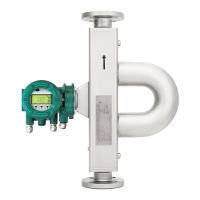
7.3.1 Connection terminals
The delivery includes an operating tool for connecting the connecting cable to the
connection terminals.
Fig.30: Connection terminal circuits (transmitter on the left side, sensor on the right side)
1 Driver circuit (D+/D-) 4 Signal grounding
2 Sensor circuits (S1+/S1-, S2+/S2-) 5 Transmitter
3 Temperature measurement circuit
(TP1, TP2, TP3)
6 Sensor
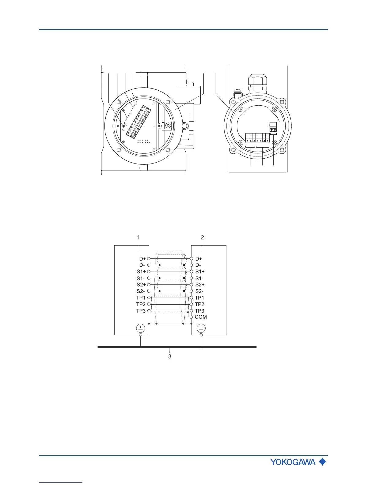
Installation of
standard connecting
cable option L
␣␣␣
Fig.31: Transmitter and sensor interconnection diagram
1 Sensor
2 Transmitter
3 Potential equalization system
 Loading...