Transmitter
General Instruction Manual
Wiring
IM 01U10B00-00EN-R, 3rd edition, 2018-07-09
59 / 90
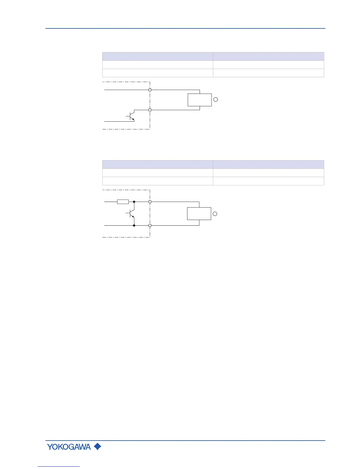
Active status
output P/Sout
Since this is a transistor contact, maximum allowed current as well as polarity and level of
output voltage must be observed during wiring.
Value
Load resistance > 1 kΩ
Internal power supply 24 V
DC
±20 %
Fig.46: Active status output connection P/Sout
① External device with load resistance
Active status
output P/Sout
with internal
pull-up resistor
Value
Internal pull-up resistor 2.2 kΩ
Internal power supply 24 V
DC
±20 %
 Loading...


