General Instruction Manual
System configuration and operation
Advanced settings
76 / 90
IM 01U10B00-00EN-R, 3rd edition, 2018-07-09
4. On the main board, set DIP switch 2 to the ON position using a sharp-pointed object.
5. Screw display cover back onto transmitter housing.
6. Tighten the locking screw by turning it counterclockwise with an Allen wrench (size:
3.0).
ð Symbol appears in the top right corner of the display.
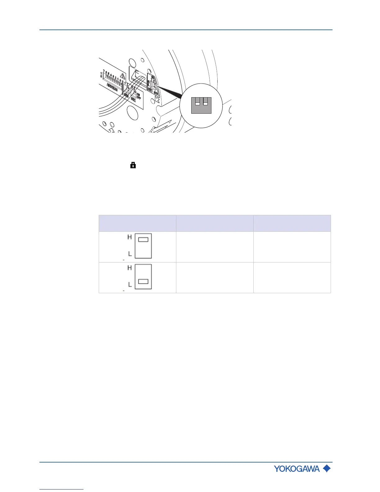
Setting the Burnout mode
The flow meter is equipped with a Burnout function. The Burnout mode can be set via
DIP SW1-1 behind the display.
Factory setting
The factory setting of the Burnout mode is High.
SW1-1 position Burnout mode Output value if Burnout
in mA
High 21.6
Low 2.4
 Loading...


