IM 05P02C41-15EN page 12/14
Parameter n=1 n=2 n=3 n=4 n=5 n=6 n=7 n=8
EHYn
ALn
VTn
HYn
DYNn
n:
alarm
number
n
PV-related Setting Parameter
Menusymbol: (PVS)
Parameter
symbol
Name of Parameter Setting Range
Initial
value
User
setting
Display
level
(BS)
PVinputbias
-100.0to100.0%ofPVinputrange
span(EUS)
0.0%of
PVinput
range
span
EASY
(FL)
PVinputlter OFF,1to120s OFF
n
PID Setting Parameter
Menusymbol: (PID)
Parameter
symbol
Name of Parameter Setting Range
Initial
value
User
setting
Display
level
(P)
Proportionalband
Heating-sideproportion-
alband(inHeating/cool-
ingcontrol)
0.0
to999.9%
When0.0%isset,itoperatesas
0.1%.
Heating-sideON/OFF
controlapplies
when0.0%inHeating/coolingcontrol
5.0%
EASY
(I)
Integraltime
Heating-sideintegraltime
(inHeating/coolingcontrol)
OFF:Disable
1to6000s
240s
(D)
Derivativetime
Heating-sidederivativetime
(inHeating/coolingcontrol)
OFF:Disable
1to6000s
60s
(OH)
Controloutputhighlimit
Heating-sidecontrol
outputhighlimit(in
Heating/coolingcontrol)
-4.9to105.0%,(OL<OH)
InHeating/coolingcontrol:0.1to
105.0%(OL<OH)
100.0%
(OL)
Controloutputlowlimit
Heating-sidecontrol
outputlowlimit(inHeat-
ing/coolingcontrol)
-5.0
to104.9%,(OL<OH),SD:Tight
shut
InHeating/cooling
control:0.0to
104.9%(OL<OH)
0.0%
(MR)
Manual reset
EnabledwhenintegraltimeisOFF.
Themanualresetvalueequalsthe
outputvaluewhenPV=SP.
-5.0to105.0%
50.0%
(HYS)
Hysteresis(inON/OFF
control or Position
proportionalcontrol)
Heating-sideON/OFF
controlhysteresis(in
Heating/coolingcontrol)
InON/OFFcontrol:0.0to100.0%of
PVinputrangespan(EUS)
InHeating/coolingcontrolorPosition
proportionalcontrol:0.0to100.0%
In
ON/OFF
control:
0.5%of
PVinput
range
span
In
Heating/
cooling
control
or
Position-
proportional
control:
0.5%
(HY.UP)
Upper-sidehysteresis
(inON/OFFcontrol)
0.0to100.0%ofPVinputrange
span(EUS)
0.5%
ofPV
input
range
span
(HY.LO)
Lower-sidehysteresis
(inON/OFFcontrol)
0.5%
ofPV
input
range
span
(DR)
Direct/reverseaction
switch
RVS:
Reverseaction
DIR:Directaction
RVS STD
(Pc)
Cooling-sidepropor-
tionalband
0.0to999.9%
(Cooling-sideON/OFF
controlap-
plieswhen
0.0%inHeating/cooling
control)
5.0%
EASY
(Ic)
Cooling-sideintegral
time
OFF:Disable
1
to6000s
240s
(Dc)
Cooling-sidederivative
time
OFF:Disable
1
to6000s
60s
(OHc)
Cooling-sidecontrol
outputhighlimit
0.1to105.0%,(OLc<OHc) 100.0%
(OLc)
Cooling-sidecontrol
output low limit
0.0to104.9%,(OLc<OHc) 0.0%
(HYSc)
Cooling-sideON/OFF
control hysteresis
0.0to100.0% 0.5%
(DB)
Outputdeadband(in
Heating/coolingcontrol
or Position proportional
control)
InHeating/cooling
control:-100.0to
50.0%
InPositionproportionalcontrol:1.0
to10.0%
3.0%
(PO)
Preset output
Heating-sidepreset
output(inHeating/cool-
ingcontrol)
In
RESETmode,xedcontroloutput
canbegenerated.InPositionpropor
-
tionalcontrol,
Valveopeningcanbe
set;-5.0to105.0%
0.0%
(POc)
Cooling-sidepreset
output
InRESET
mode,cooling-sidexed
controloutputcanbegenerated.
-5.0to105.0%
0.0% EASY
Ifyou
areusingtwoormoregroupsofPIDparameters,usethefollowingtabletorecordtheirsettingvalues.
Parameter n=2 n=3 n=4 n=5 n=6 n=7 n=8 R
P
I
D
OH
OL
MR
HYS
HY.UP
HY.LO
DR
Pc
Ic
Dc
OHc
OLc
HYSc
DB
PO
POc
n:
group
number
n
Tuning Parameter
Menusymbol:
(TUNE)
Parameter
symbol
Name of Parameter Setting Range
Initial
value
User
setting
Display
level
(SC)
Super function
OFF:Disable
1:Overshootsuppressingfunction
(normalmode)
2:Huntingsuppressingfunction
(stablemode)
Enablesto
answerthewider
characteristicchangescompared
with response mode.
3:Huntingsuppressingfunction
(responsemode)
Enablesquick
follow-upandshort
convergingtimeofPVforthe
changedSP.
4:Overshootsuppressingfunction
(strongsuppressingmode)
Note:Setpoints
2and3mustbe
usedinPIDcontrolorPIcontrol.
Disabledinthefollowingcontrols:
1)ON/OFF
control,2)PDcontrol,
3)Pcontrol,4)Heating/cooling
control.
Donot
usethefunctionforthe
control processes with response
suchasoworpressurecontrol.
OFF EASY
(AT.TY)
Auto-tuningtype
0:Normal
1:Stability
0 STD
(AR)
Anti-resetwindup
(excessintegration
prevention)
AUTO,
50.0to200.0% AUTO
STD
(OPR)
Outputvelocitylimiter
OFF:Disable
0.1to100.0%/s
OFF
(MPON)
Manual preset output
numberselection
SelecttheoutputusedinMANmode
whenswitchedfromAUTOtoMAN
mode.
OFF:HoldthecontroloutputinAUTO
mode(bumpless)
1:Usemanualpresetoutput1(outputbump)
2:Usemanualpresetoutput2(outputbump)
3:Usemanualpresetoutput3(outputbump)
4:Usemanualpresetoutput4(outputbump)
5:Usemanualpresetoutput5(outputbump)
OFF
to
(MPO1toMPO5)
Manual preset output 1
to 5
-5.0to105.0%
However,outputislimitedtothe
outputhighlimitandlowlimit.
0.0%
Table
below
Usethe
followingtabletorecordthemanualpresetoutputsettingvalue.
Parameter n=1 n=2 n=3 n=4 n=5
MPOn
n
Zone Control Parameter
Menusymbol: (ZONE)
Parameter
symbol
Name of Parameter Setting Range
Initial
value
User
setting
Display
level
to
(RP1toRP7)
Referencepoint1to7
Set reference points at which switch
-
ingis
carriedoutbetweengroupsof
PIDconstantsaccordingtothegiven
temperaturezone.
0.0to100.0%ofPVinputrange(EU)
(RP1≤RP2≤RP3≤RP4≤RP5≤
RP6≤RP7)
100.0%
ofPV
input
range
Table
below
STD
(RHY)
ZonePIDswitching
hysteresis
Hysteresiscan
besetforswitchingat
a reference point.
0.0to10.0%ofPVinputrangespan
(EUS)
0.5%
ofPV
input
range
span
STD
(RDV)
Referencedeviation
SetadeviationfromSP.ThePIDfor
referencedeviationisusedifthere
isalargerdeviationthanthepreset
referencedeviation.
OFF:Disable
0.0+1digitto100.0%ofPVinput
rangespan(EUS)
OFF STD
ForZonecontrol,setthesetupparameterZON(zonePIDselection)toZonePIDselection.
Usethefollowingtabletorecordthereferencepointsettingvalue.
Parameter n=1 n=2 n=3 n=4 n=5 n=6 n=7
RPn
n
P Parameter (for Ladder Program)
Menusymbol: (PPAR)
Parameter
symbol
Name of Parameter Setting Range
Initial
value
User
setting
Display
level
to
(P01toP10)
P01toP10parameter
-19999to30000(Setadecimalpoint
positionusingLL50AParameterSet-
tingSoftware.)
0
T
able
below
STD
Parameter n=01 n=02 n=03 n=04 n=05 n=06 n=07 n=08 n=09 n=10
Pn
n
10-segment Linearizer-1, -2 Setting Parameter
Menusymbol: (PYS1)
(PYS2)
Parameter
symbol
Name of Parameter Setting Range
Initial
value
User
setting
Display
level
(PYS)
10-segmentlinearizer
selection
OFF:Disable
PV
:PVanaloginput
RSP:RSPanaloginput
AIN2:AIN2analoginput
AIN4:AIN4analoginput
PVIN:PVinput
OUT:OUTanalogoutput
OUT2:OUT2analogoutput
RET:RETanalogoutput
PV
(CTLM
:
SGL)
STD
(A1)
10-segmentlinearizer
input 1
-66.7to105.0%ofinputrange(EU)
Outputlinearizer:-5.0to105.0%
0.0%
(B1)
10-segmentlinearizer
output 1
10-segmentlinearizerbias:-66.7to
105.0%ofinputrangespan(EUS)
10-segmentlinearizerapproximation:
-66.7to105.0%ofinputrange(EU)
Outputlinearizer:-5.0to105.0%
0.0%
to ,
to
(A2toA11,B2to
B11)
10-segmentlinearizer
input 2 to 11
10-segmentlinearizer
output 2 to 11
SameasA1andB1
Same
asA1
and
B1
(PMD)
10-segmentlinearizer
mode
0:10-segment
linearizerbias
1:10-segmentlinearizerapproxima-
tion
0
Usethe
followingtabletorecordthe10-segmentlinearizerinputandoutputsettingvalues.
Parameter n=2 n=3 n=4 n=5 n=6 n=7 n=8 n=9 n=10 n=11
An
Bn
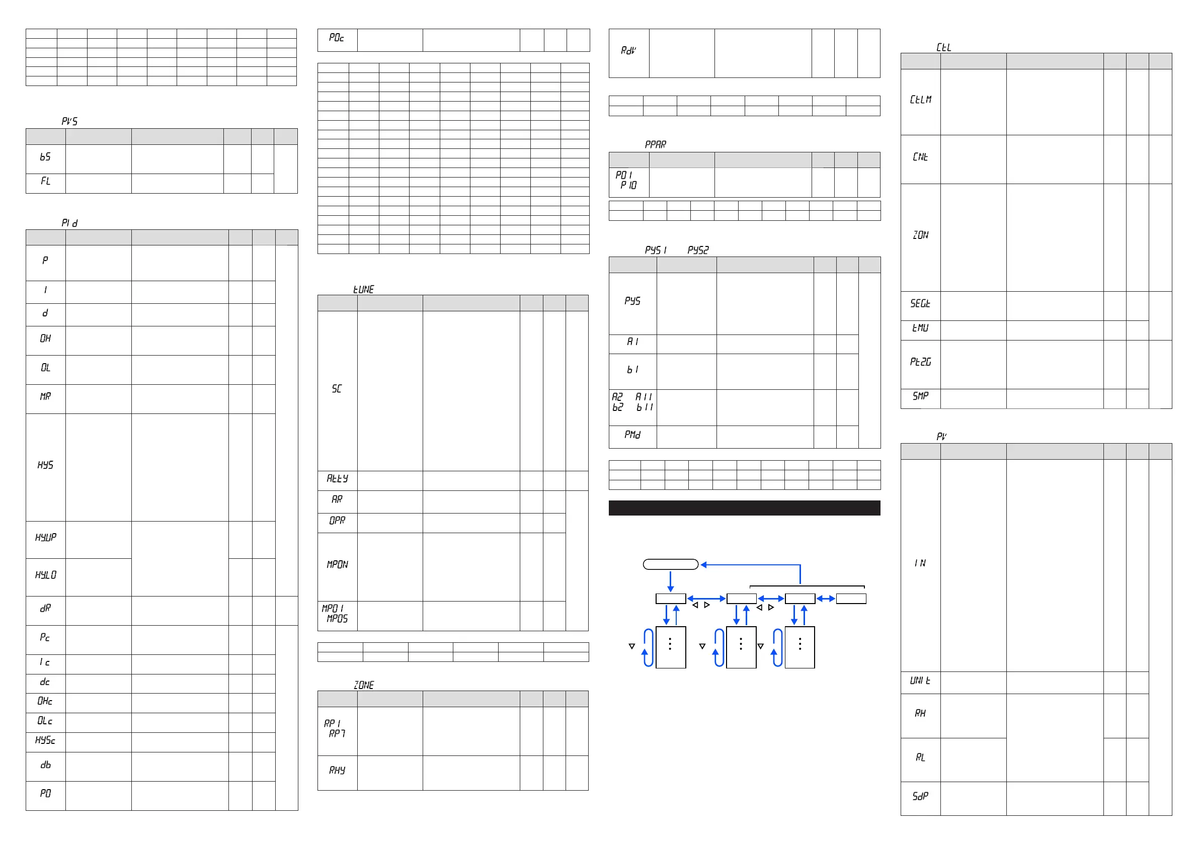
Setup Parameters
HolddownthePARAMETERkeyandLeftarrowkeysimultaneouslyfor3secondsto
movefromtheOperationDisplayorOperationParameterSettingDisplaytotheSetup
ParameterSettingDisplay.
PresstheDISPLAYkeyoncetoreturntotheOperationDisplay.
Menu
key
key key
key
key
Operation Dsipaly
Parameter
Parameter
Parameter
Parameter
Parameter
Parameter
END
Menu
END
Menu END
END
Menu Display and
P a r a m e t e r
Setting Display
are changed in a
circular pattern.
Hold down PARAMETER key and
Left arrow key simultaneously for 3 sec.
DISPLAY key
PARAMETER key
SET/ENTER key
Move to the Operation Parameter Setting Display: Hold down the PARAMETER key for 3 sec.
Operation for Setting
· Toselecttheparametersettingdisplayedastheinitialvalue,presstheDownarrow
keytomovetothenextparameter.
· Tochangeandsettheparametersetting,presstheSET/ENTERkeytostarttheset
-
pointblinking.
Theblinkingstateallowsyoutomakechanges(settingmode).Usethe
Up/Down/Left/Rightarrowkeystochangethesetpoint.PresstheSET/ENTERkeyto
registerthesetting.
NotethattherearesomeparameterswhicharenotdisplayeddependingontheModel
andSufxcodes,controlmode(CTLM),control type(CNT), etc.Theparametersfor
professionalsetting mode(LEVL:PRO) arenotdescribedinthis manual.SeeUser’s
Manual.
n
Control Function Setting Parameter
Menusymbol: (CTL)
Parameter
symbol
Name of Parameter Setting Range
Initial
value
User
setting
Display
level
(CTLM)
Controlmode
Whenusingthecontrolsotherthan
Single-loopcontrol,seeUser's
Manual.
SGL STD
SGL:Single-loop
control
CAS1:Cascadeprimary-loopcontrol
CAS:Cascadecontrol
PVSW:
LoopcontrolwithPVswitching
PVSEL:LoopcontrolwithPVauto-
selector
(CNT)
Controltype
PID:PIDcontrol
ONOF:ON/OFFcontrol(1pointof
hysteresis)
ONOF2:ON/OFF
control(2pointsof
hysteresis)
H/C:Heating/cooling
control
PID
or
H/C
(for
Heating/
Cooling
type)
EASY
(ZON)
ZonePIDselection
0:SegmentPIDselection
1:
ZonePIDselection(selectionbyPV)
2:ZonePIDselection(selectionby
targetSP)
4:
ZonePIDselection(selectionbySP)
5:LocalPIDselection
*Ifsetto“SegmentPIDselection,”
allowsPIDconstantstobeselected
foreachsegments.
*Ifsetto“ZonePIDselection,”
automaticallyselectsPIDconstants
accordingtotherangesetinthe
Referencepoint.
*Ifsetto“LocalPIDselection,”local
PIDisselectedirrespectiveofthe
operation modes.
1 STD
(SEG.T)
Segmentsettingmethod
TIME:Segmenttimesetting
TM.RT:Segmentramp-ratesetting
*Note:Achangeofsettingdeletesa
programpattern.
TIME
EASY
(TMU)
Programtimeunit
HH.MM: hour.minute
MM.SS: minute.second
HH.MM
(PT2.G)
Programpattern-2
retransmission
OFF:Notused.
ON:used.
*
Thecontrollercanserveasaprogram
patterngenerator.
*Retransmissionoutputtypes(RTS,
O1RS,orO2RS)needtobesetto
SP2.
OFF
STD
(SMP)
Inputsamplingperiod
(controlperiod)
100:100ms,200:200ms 200
n
PV Input Setting Parameter
Menusymbol: (PV)
Parameter
symbol
Name of Parameter Setting Range
Initial
value
User
setting
Display
level
(IN)
PVinputtype
OFF:Disable
K1:-270.0to1370.0
0
C/-450.0to2500.0
0
F
K2:-270.0to1000.0
0
C/-450.0to2300.0
0
F
K3:-200.0to500.0
0
C/-200.0to1000.0
0
F
J:-200.0to1200.0
0
C/-300.0to2300.0
0
F
T1:-270.0to400.0
0
C/-450.0to750.0
0
F
T2:0.0to400.0
0
C/-200.0to750.0
0
F
B:0.0to1800.0
0
C/32to3300
0
F
S:0.0to1700.0
0
C/32to3100
0
F
R:0.0to1700.0
0
C/32to3100
0
F
N:-200.0to1300.0
0
C/-300.0to2400.0
0
F
E:-270.0to1000.0
0
C/-450.0to1800.0
0
F
L:-200.0to900.0
0
C/-300.0to1600.0
0
F
U1:-200.0to400.0
0
C/-300.0to750.0
0
F
U2:0.0to400.0
0
C/-200.0to1000.0
0
F
W:0.0to2300.0
0
C/32to4200
0
F
PL2:0.0to1390.0
0
C/32.0to2500.0
0
F
P2040:0.0to1900.0
0
C/32to3400
0
F
WRE:0.0to2000.0
0
C/32to3600
0
F
JPT1:-200.0to500.0
0
C/-300.0to1000.0
0
F
JPT2:-150.0to150.0
0
C/-200.0to300.0
0
F
PT1:-200.0to850.0
0
C/-300.0to1560.0
0
F
PT2:-200.0to500.0
0
C/-300.0to1000.0
0
F
PT3:-150.00to150.00
0
C/-200.0to300.0
0
F
0.4-2V:0.400to2.000V
1-5V:1.000to5.000V
4-20:4.00to20.00mA
0-2V:0.000to2.000V
0-10V:0.00to10.00V
0-20:0.00to20.00mA
-1020:-10.00to20.00mV
0-100:0.0to100.0mV
OFF
EASY
(UNIT)
PVinputunit
-:Nounit,C:DegreeCelsius,
-:Nounit,--:Nounit,---:Nounit,
F:Degree
Fahrenheit
C
(RH)
MaximumvalueofPV
inputrange
Dependsontheinputtype.
-Fortemperatureinput-
Setthetemperaturerangethatis
actuallycontrolled.(RL<RH)
-Forvoltage/currentinput-
Settherangeofavoltage/cur
-
rentsignal
thatisapplied.
Thescaleacrosswhichthevoltage
/currentsignalisactuallycontrolled
shouldbesetusingthemaximum
valueofinputscale(SH)andmini
-
mumvalue
ofinputscale(SL).
(Inputisalways0%whenRL=RH.)
Depends
on the
input type
(RL)
MinimumvalueofPV
inputrange
Depends
on the
input type
(SDP)
PVinputscaledecimal
point position
0:Nodecimalplace
1:Onedecimalplace
2: Two decimal places
3: Three decimal places
4: Four decimal places
Depends
on the
input type

 Loading...


