IM 05P02C41-15EN page 9/14
Contents
1. Monitoring-purposeOperationDisplaysAvailableduringOperation
2. Performing/CancelingAuto-tuning
3. SelectingProgramPatternNumber(PT.No)
4. SwitchingbetweenRUNandRESET
5. SwitchingbetweenAUTOandMAN
6. ManipulatingControlOutputinManualMode
7. Enabling/DisablingHold-mode(HOLD)ofProgramOperation
8. ChangingProgramSetpointswheninHold-mode(HOLD)
9. Executing“Advance”(ADV)Function
10.SwitchingtoLocal-mode(LOCAL)Operation
11.ChangingSetpointsduringLocal-mode(LOCAL)Operation
12.SwitchingtoRemote-mode(REMOTE)Operation
13.Troubleshooting
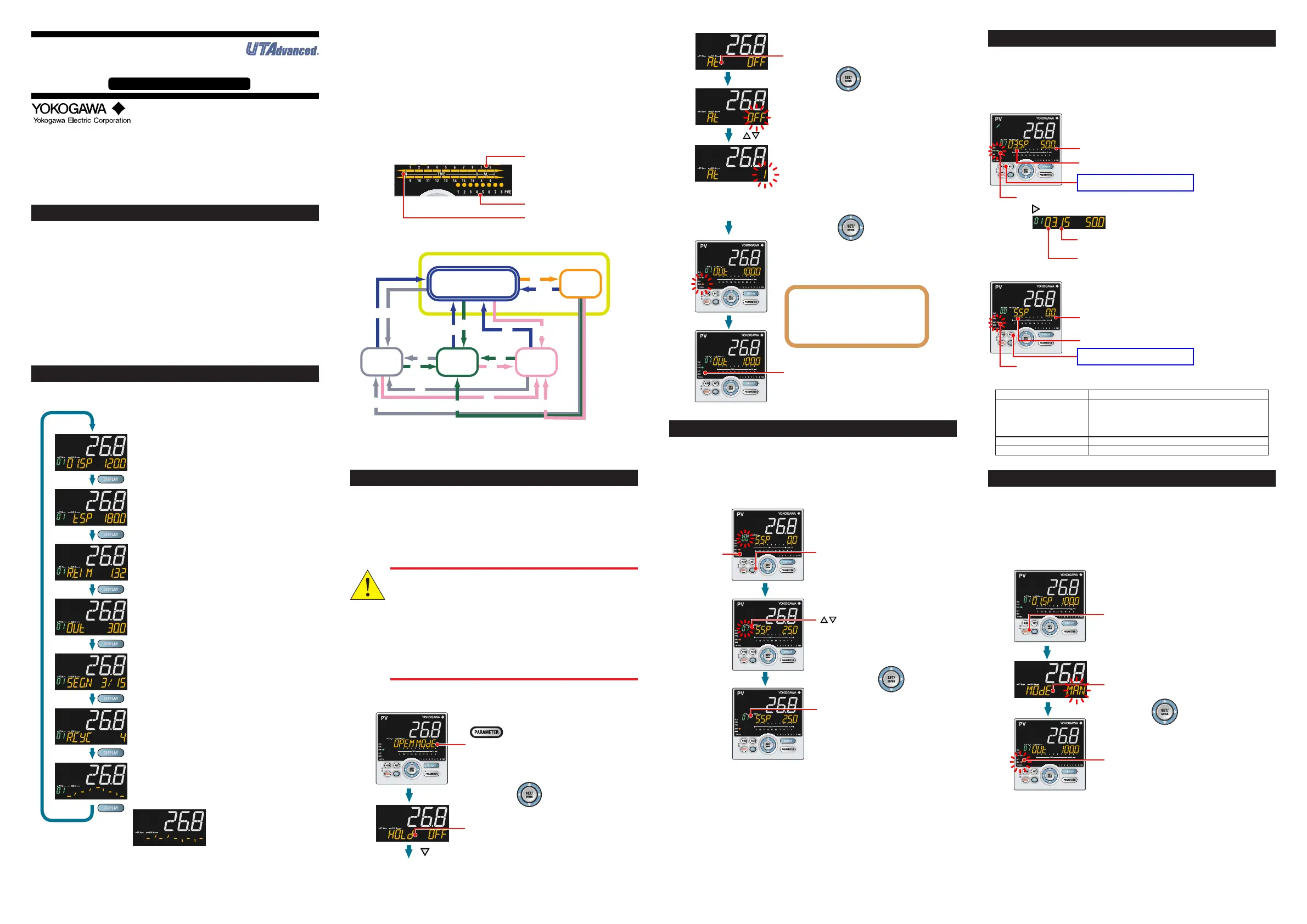
1. Monitoring-purpose Operation Displays Available during Operation
■
Operation Display Switching Diagram
SP Display
TSP Display
Remaining Segment-time Display
Segment Number Display
Remaining Repetition Display
Program Pattern Display
OUT Display / Heating/cooling OUT Display
Displays the target setpoint (SP) on Setpoint display.
Displays "SSP" during reset-mode.
Displays "L.SP" during local-mode operation.
Displays "R.SP" during remote-mode operation.
Displays the final target setpoint (TSP) on Setpoint display
only during program operation.
Displays the remaining segment time (R.TIM) on Setpoint
display during program operation.
Displays the segment number (SEG.N) for which operation is
in progress, the number of segments included in the selected
program pattern.
Displays the number of remaining repetitions (R.CYC) on
Setpoint display. This display is displayed only when the
repeat function is set and the operation mode is PROG.
Displays the program pattern (overview) on Setpoint display.
Program pattern display can be scrolled using
Up/Down/Left/Right arrow keys.
Soak and ramp can be displayed.
Displays the measured input value on PV display.
Displays the control output value (OUT) on Setpoint display.
Displays the control output values (C.H.) of heating and
cooling sides on Setpoint display (C.H. can be changed in
manual mode).
AftershowingtheProgramPatternDisplay,presstheDISPLAYkeytoshowthefol-
lowingdisplaysconditionally.
Fordetails,seeUser’sManual.
Standard, Position Proportional, and Heating/Cooling Types
• SELECTDisplays1to5(whichappearwhenregistered)
• AnalogInputDisplay(displayonly)(factorydefault:non-display)
• PositionProportionalComputationOutput Display(displayonly)(factory default:
non-display)
• PID
NumberDisplay(displayonly)(factorydefault:non-display)
• Alarm-5to-8StatusDisplay(whichappearwhenregistered)
•
HeaterBreakAlarm-1CurrentDisplay(displayonly)(forheaterbreakalarmoptiononly)
•
HeaterBreakAlarm-2CurrentDisplay(displayonly)(forheaterbreakalarmoptiononly)
■
Event Display
Timeevent(TME),PVevent(PVE)andalarm(AL)aredisplayedontheBar-graph
displayandtheEventIndicator.(factorydefaultsetting)
PV event 1 to 8
Time event 1 to 16
Alarm 1 to 4
■
Operation Display Switching Diagram
*1: For another operation, when select
ADV=ON and starts program
operation. In this case, the segment
is advanced.
(1) Press RUN key for 1 s.
(2) Press RST key for 1 s.
(3) Press MODE key, select HOLD=ON and press SET/ENT key.
(4) Press MODE key, select HOLD=OFF and SET/ENT key.
(5) Press MODE key, select LOC=ON and press SET/ENT key.
(6) Press MODE key, select REM=ON and press SET/ENT key.
Reset
Remote-mode
operation
Local-mode
operation
Program
operation
Hold-mode
operation
(*1)
(1)
(1)
(2)
(2)
(2)
(2)
(3)
(1) (4)
(5)
(5)
(5)
(5)
(6)
(6)
(6)
(6)
(1)
2. Performing/Canceling Auto-tuning
Auto-tuningshouldbeperformedaftersettingaprogrampattern.
Makesurethatthecontrollerisinautomaticmode(AUTO)andinrunmode(RUN)
before auto-tuning. Forsetting toAUTO, see “5. Switching between AUTO and
MAN,”andforsettingtoRUN,see“4.SwitchingbetweenRUNandRESET.”
Ifthesetpointisknowninadvanceorauto-tuningdoesnotndanyappropriatePID
constants,setthePIDmanually.ForsettingthePIDmanually,seeUser’sManual.
Do not perform auto-tuning for the following processes.
Tune PID manually.
• Processes with
fast response such as flow rate control and pres-
sure control.
•
Processes which
do not allow the output to be turned on and off
even temporarily.
• Pr
ocesses which prohibit severe output changes at control
valves (or other actuators).
• Proc
esses in which product quality can be adversely affected if
PV values fluctuate beyond their allowable ranges.
1.
2.
3.
4.
OFF blinks.
Blinks during the change.
The MAN lamp goes off, which means that
the auto-tuning completed normally.
5.
6.
7.
8.
Show the Operation Display.
Hold down the PARAMETER key for 3 seconds
to display MODE menu.
Press the SET/ENTER key.
Press the SET/ENTER key.
Press the SET/ENTER key.
The parameter HOLD (Pause/cancel release
of program operation) is displayed (during
program operation.)
Press the Down arrow key until the parameter AT appears.
The parameter AT (auto-tuning switch) is displayed.
Press the Up/Down arrow keys to display the required setpoint.
The setting range is 1 to 8 (represent group numbers) or R.
To perform auto-tuning for the PID of group 1, set the parameter AT to 1.
To quit the auto-tuning, set the parameter to OFF.
The setpoint has been registered.
This starts auto-tuning.
The limiter can be set to the output during
auto-tuning.
For details, see User’s Manual.
During auto-tuning,
• The MAN lamp blinks.
• The OUT symbol appears.
• The output values at 100.0% and 0%
appear alternately.
3.
Selecting Program Pattern Number (PT.No)
Programpatternnumberselectioncanbeperformedusinganyofthefollowing:(1)
key,(2)Parameter,(3)Contactinput,and(4)Communication.
Thefollowingshowsanexampleofchangingtheprogrampatternnumber(PTNO.)
to1usingthekey.
ProgrampatternnumbercanbeselectedwhenthecontrollerisinaRESETmode.
1.
2.
3.
4.
RST lamp
is lit.
PTNO. has been changed to 1.
Blinks during the change.
Show the Operation Display.
Press the SET/ENTER key.
Press the PTN key.
Press the Up/Down arrow keys
to display the required setpoint.
Operation
Guide
This operation guide describes key entries for operating the UP55A.
For operations using external contact inputs, see “DI” of “6. Terminal Wiring Diagrams”
in “Installation and Wiring.”
If you cannot remember how to carry out an operation during setting, press the
DISPLAY key once. This brings you to the display (Operation Display) that appears at
power-on.
The scrolling guide is displayed on PV display in the Parameter Setting Display.
This guide can be turned on/off with the MODE key.
UP55A
Program Controller
Operation Guide for Single-loop Control
Operations
4.
Switching between RUN and RESET
RUNandRESETswitchingcanbeperformedusinganyofthefollowing:(1)key,(2)
Contactinput,(3)Parameter,and(4)Communication.
Thefollowingshowsanexampleofswitchingusingthekey.
Fordetailsofotherswitchingmethodsandthedisplayappearingwhentheoperation
isstarted,seeUser’sManual.
Display in RUN mode
Starting target setpoint
RST lamp is lit.
Display in RESET mode
Current segment number and symbol (SP)
PRG lamp is lit.
Program setpoint
Press RUN key for 1 s.
Symbol SSP
The number of segments included in the selected
program pattern.
The segment number for which operation is in progress.
The figure below is displayed while the right arrow key is held down.
Press RST key for 1 s.
Whenthecontrollerisstopped,inputandoutputsareasfollows:
PVinput DisplaysthePVvalue.
Controloutput WhenthezonePIDselectionparameter(ZON)issettosegment
PIDselection,thepresetoutputvalueforthePIDgroupnumber1
isoutput.WhenthezonePIDselectionparameter(ZON)issetto
otherthansegmentPIDselection,thepresetoutputvalueforthe
PIDgroupnumberforwhichzonecontrolisperformedisoutput.
Eventoutput Turnstheoutputoffincaseofanevent.
Alarmoutput Turns the output on in case of an alarm.
5. Switching between AUTO and MAN
AUTOandMANswitchingcan beperformedusingany ofthe following:(1)MODE
key,(2)Contactinput,(3)Contactinput,and(4)Communication.
ThefollowingshowsanexampleofswitchingusingtheMODEkey.
WhenAUTOandMANswitching functionisassignedtothe contactinput,andthe
contactinputisON,theswitchingbykeyoperationcannotbeperformed.
Fordetails,seeUser’sManual.
Displays ”MODE MAN” in AUTO mode.
Displays ”MODE AUTO” in MAN mode.
1.
2.
3.
Press MODE key several times.
Show the Operation Display.
4.
MAN lamp is lit in MAN mode.
Press the SET/ENTER key.
WhenAUTOisswitchedintoMAN,thecontroloutputvalueinAUTOmodeisheld.
Thecontrollercanbeoperatedmanuallyfromtheholdvalue.
Ifthe manualpreset outputis set(MPONparameter≠OFF),thecontrollercanbe
operatedmanuallyfromthearbitraryoutputvalue(MPO1toMPO5parameters).

 Loading...


