IM 05P02C41-15EN page 13/14
(SH)
MaximumvalueofPV
input scale
-19999to30000,(SL<SH),
|SH-SL|≤30000
Depends
on the
input type
EASY
(SL)
MinimumvalueofPV
input scale
Depends
on the
input type
(BSL)
PVinputburnoutaction
OFF:Disable
UP:Upscale
DOWN:Downscale
Depends
on the
input type
STD
(A.BS)
PVanaloginputbias
-100.0to100.0%ofPVinputrange
span(EUS)
0.0%of
PVinput
range
span
(A.FL)
PVanaloginputlter
OFF,1to120s
OFF
W:W-5%Re/W-26%Re(HoskinsMfg.Co.).ASTME988,WRE:W97Re3-W75Re25
n
RSP Input Setting Parameter (E1-terminal Area)
Menusymbol: (RSP)
Parameter
symbol
Name of Parameter Setting Range
Initial
value
User
setting
Display
level
(IN)
RSPremoteinputtype
0.4-2V:0.400to2.000V
1-5V:1.000to5.000V
0-2V:0.000to2.000V
0-10V:0.00to10.00V
0-125:0.000to1.250V
Foroption/DR,RSPremoteinput
typeissameasPVinputtype
1-5V
EASY
(UNIT)
RSPremoteinputunit
-:Nounit,C:DegreeCelsius,
-:No
unit,--:Nounit,---:Nounit,
F:Degree
Fahrenheit
C
(RH)
MaximumvalueofRSP
remoteinputrange
Dependsontheinputtype.
-Fortemperature(/DRoption)input-
Setthetemperaturerangethatis
actuallycontrolled.(RL<RH)
-Forvoltage/current(/DRoption)input-
Settherangeofavoltage/current
signalthatisapplied.
Thescaleacrosswhichthevoltage
/currentsignalisactuallycontrolled
shouldbesetusingthemaximum
valueofinputscale(SH)andmini
-
mumvalue
ofinputscale(SL).
(Inputisalways0%whenRL=RH.)
Depends
on the
input type
(RL)
MinimumvalueofRSP
remoteinputrange
Depends
on the
input type
(SDP)
RSPremoteinputscale
decimal point position
0:Nodecimalplace
1:Onedecimalplace
2: Two decimal places
3: Three decimal places
4: Four decimal places
Depends
on the
input type
(SH)
MaximumvalueofRSP
remote input scale
-19999to30000,(SL<SH),
|SH
-SL|≤30000
Depends
on the
input type
(SL)
MinimumvalueofRSP
remote input scale
Depends
on the
input type
(BSL)
RSPremoteinputbum-
out action
OFF:
Disable
UP:Upscale
DOWN:Downscale
Depends
on the
input type
STD
(RTD.S)
RTDwiringsystem
3-W:3-wiresystem
4-W:4-wiresystem
(TheLL50AParameterSettingSoft-
wareis
requiredtouseRSPterminals
inputasPV.)
3-W
n
AIN2/AIN4 Aux. Analog Input Setting Parameter
(E2/E4-terminal Area)
Menusymbol: (AIN2)
(AIN4)
Parameter
symbol
Name of Parameter Setting Range
Initial
value
User
setting
Display
level
(IN)
AIN2/AIN4aux.analog
input type
0.4-2V:0.400to2.000V
1-5V:1.000to5.000V
0-2V:0.000to2.000V
0-10V:0.00to10.00V
0-125:0.000to1.250V
1-5V
EASY
(UNIT)
AIN2/AIN4aux.analog
input unit
-:Nounit
C:DegreeCelsius
-:Nounit
--:Nounit
---:Nounit
F:DegreeFahrenheit
C
(RH)
MaximumvalueofAIN2/
AIN4aux.analoginput
range
Dependson
theinputtype.
Settherangeofavoltagesignalthat
is applied.
Thescaleacrosswhichthevoltage
signalisactuallycontrolledshouldbe
setusingthemaximumvalueofinput
scale(SH)andminimumvalueof
inputscale(SL).
(Inputisalways0%whenRL=RH.)
Depends
on the
input type
(RL)
MinimumvalueofAIN2/
AIN4aux.analoginput
range
Depends
on the
input type
(SDP)
AIN2/AIN4aux.analog
input scale decimal point
position
0:No
decimalplace
1:Onedecimalplace
2: Two decimal places
3: Three decimal places
4: Four decimal places
Depends
on the
input type
(SH)
MaximumvalueofAIN2/
AIN4aux.analoginput
scale
-19999to
30000,(SL<SH),
|SH-SL|≤30000
Depends
on the
input type
(SL)
MinimumvalueofAIN2/
AIN4aux.analoginput
scale
Depends
on the
input type
(BSL)
AIN2/AIN4aux.analog
inputburnoutaction
OFF:Disable
UP:Upscale
DOWN:Downscale
Depends
on the
input type
STD
n
Input Range, SP Limiter Setting Parameter
Menusymbol: (MPV)
Parameter
symbol
Name of Parameter Setting Range
Initial
value
User
setting
Display
level
(P.UNI)
ControlPVinputunit
-:Nounit
C:DegreeCelsius
-:Nounit,--:Nounit,---:Nounit
F:DegreeFahrenheit
Same
asPV
input
unit
STD
(P.DP)
ControlPVinputdecimal
point position
0:Nodecimalplace
1:Onedecimalplace
2: Two decimal places
3: Three decimal places
4: Four decimal places
1
(P.RH)
Maximumvalueof
controlPVinputrange
-19999to30000,(P.RL<P.RH),
|P.RH-P.RL|≤30000
Depends
on the
input type
(P.RL)
Minimumvalueofcontrol
PVinputrange
Depends
on the
input type
(SPH)
SPhighlimit
0.0to100.0%ofPVinputrange(EU),
(SPL<SPH)
Placelimitsontheprogramsetpoints
or the local setpoints when the con-
trolleris
inprogramoperation.
*Placesthelimitontheprogram
setpoint, local setpoint, or remote
setpointduringprogramoperation.
*WhenLP2lampison,SPHand
SPLlimittheprogramsetpointfor
programpattern2retransmission.
100.0%
ofPV
input
range
(SPL)
SP low limit
0.0%
ofPV
input
range
n
Output Setting Parameter
Menusymbol: (OUT)
Parameter
symbol
Name of Parameter Setting Range
Initial
value
User
setting
Display
level
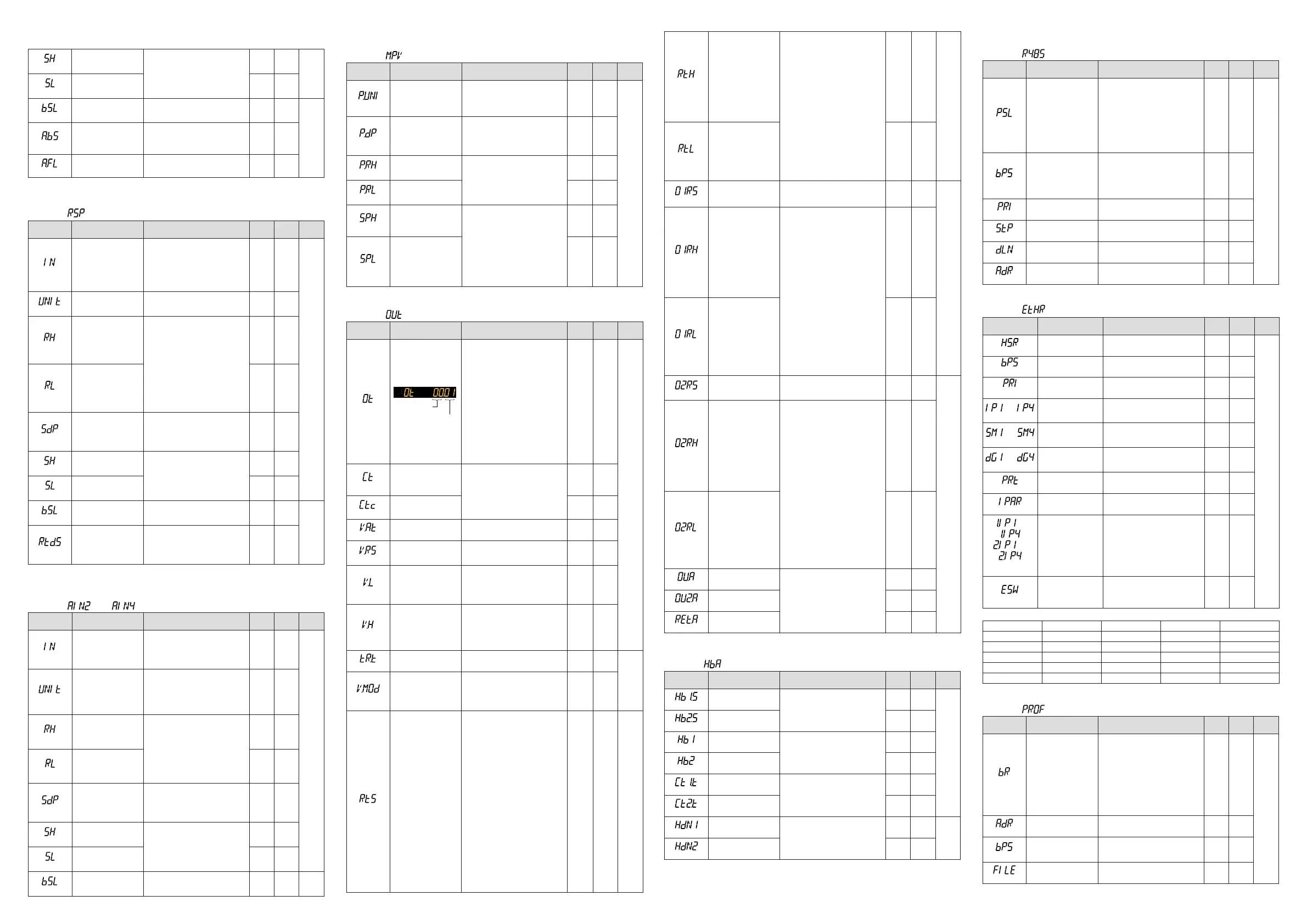
(OT)
Outputtypeselection
Upper two
digits
Lower two
digits
ControloutputorHeating-sidecontrol
output(Lowertwodigits)
00:OFF
01:OUTterminals(voltagepulse)
02:OUTterminals(current)
03:OUTterminals(relay/triac)
04:OUT2terminals(voltagepulse)
05:OUT2terminals(current)
06:OUT2terminals(relay/triac)
Cooling-sidecontroloutput(Uppertwodigits)
00:OFF
01:OUTterminals(voltagepulse)
02:OUTterminals(current)
03:OUTterminals(relay/triac)
04:OUT2terminals(voltagepulse)
05:OUT2terminals(current)
06:OUT2terminals(relay/triac)
Standard
type:
00.03
Heating/
cooling
type:
06.03
EASY
(CT)
Controloutputcycletime
Heating-sidecontrol
outputcycletime(in
Heating/coolingcontrol)
0.5to1000.0s
30.0s
(CTc)
Cooling-sidecontrol
output cycle time
30.0s
(V.AT)
Automaticvalveposition
adjustment
OFF:Stop
automaticadjustment
ON:Startautomaticadjustment
OFF
(V.RS)
Valvepositionsetting
reset
SettingV
.RStoONresetsthevalve
adjustmentsettingsandcausesthe
indication“V.RS”toblink.
OFF
(V.L)
Fully-closedvalveposi-
tionsetting
PressingtheSET/ENTERkeywithvalve
positionsettothefully-closedposition
byDownarrowkeycausestheadjusted
valuetobestored.WhenV.Ladjustment
iscompleted,V.Lstopsblinking.
-
(V.H)
Fully-openedvalveposi-
tionsetting
Pressing
theSET/ENTERkeywith
valvepositionsettothefully-opened
positionbyUparrowkeycausesthe
adjustedvaluetobestored.WhenV.H
adjustmentiscompleted,V.Hstops
blinking
-
(TR.T)
Valvetravelingtime 5to300s 60s
STD
(V.MOD)
Valveadjustingmode
0:Valvepositionfeedbacktype
1:
Valvepositionfeedbacktype(moves
totheestimatingtypeifafeedback
inputerrororbreakoccurs.)
2:Valvepositionestimatingtype
0
(RTS)
Retransmissionoutput
typeofRET
OFF:Disable
PV1:PV
SP1: SP
OUT1:
OUT(Valveopening:0to100%
inPositionproportionalcontrol)
LPS:15VDClooppowersupply
PV2:Loop-2PV
SP2:Loop-2SP
OUT2:Loop-2OUT
TSP1:TargetSP
HOUT1:Heating-sideOUT
COUT1:Cooling-sideOUT
MV1:Positionproportionaloutput
(internalcomputedvalue)
TSP2:Loop-2targetSP
HOUT2:Loop-2heating-sideOUT
COUT2:Loop-2cooling-sideOUT
MV2:Loop-2positionproportional
output(internalcomputedvalue)
PV:PVterminalsanaloginput
RSP:RSPterminalsanaloginput
AIN2:AIN2terminalsanaloginput
AIN4:AIN4terminalsanaloginput
*Loop-2settingvaluesare
unavailable
inSingle-loopcontrol.
PV1 EASY
(RTH)
Maximumvalueof
retransmission output
scaleofRET
WhenRTS=PV1,SP1,PV2,SP2,
TSP1,TSP2,PV,RSP,AIN2,or
AIN4,
RTL+1digitto30000
-19999toRTH-1digit
Decimalpointposition:
WhenRTS=PV1,SP1,orTSP1,
decimal point position is same as
thatofPVinput.
WhenRTS=PV2,SP2,orTSP2,
decimal point position is same as
thatofRSPinput.
WhenRTS=PV,decimalpointposition
issameasthatofPVinputscale.
WhenRTS=RSP,decimalpointposition
issameasthatofRSPinputscale.
WhenRTS=AIN2,decimalpointposi-
tionissameasthatofAIN2scale.
WhenRTS=AIN4,decimalpointposi-
tionis
sameasthatofAIN4scale.
100%
ofPV
input
range
STD
(RTL)
Minimumvalueof
retransmission output
scaleofRET
0%
ofPV
input
range
(O1RS)
Retransmissionoutput
typeofOUTcurrent
output
Sameas
RTS
OFF
STD
(O1RH)
Maximumvalueof
retransmission output
scaleofOUTcurrent
output
WhenO1RS
=PV1,SP1,PV2,SP2,
TSP1,TSP2,PV,RSP,AIN2,orAIN4,
O1RL+1digitto30000
-19999toO1RH-1digit
Decimalpointposition:
WhenO1RS=PV1,SP1,orTSP1,
decimal point position is same as
thatofPVinput.
WhenO1RS=PV2,SP2,orTSP2,
decimal point position is same as
thatofRSPinput.
WhenO1RS=PV,decimalpointposi
-
tionis
sameasthatofPVinput
scale.
WhenO1RS
=RSP,decimalpoint
positionissameasthatofRSP
input scale.
WhenO1RS=AIN2,decimalpoint
positionissameasthatofAIN2
scale.
WhenO1RS
=AIN4,decimalpoint
positionissameasthatofAIN4
scale
-
(O1RL)
Minimumvalueof
retransmission output
scaleofOUTcurrent
output
-
(O2RS)
Retransmissionoutput
typeofOUT2current
output
Sameas
RTS
OFF
STD
(O2RH)
Maximumvalueof
retransmission output
scaleofOUT2current
output
WhenO2RS
=PV1,SP1,PV2,SP2,
TSP1,TSP2,PV,RSP,AIN2,orAIN4,
O2RL+1digitto30000
-19999toO2RH-1digit
Decimalpointposition:
WhenO2RS=PV1,SP1,orTSP1,
decimal point position is same as
thatofPVinput.
WhenO2RS=PV2,SP2,orTSP2,
decimal point position is same as
thatofRSPinput.
WhenO2RS=PV,decimalpointposi
-
tionis
sameasthatofPVinput
scale.
WhenO2RS
=RSP,decimalpoint
positionissameasthatofRSP
input scale.
WhenO2RS=AIN2,decimalpoint
positionissameasthatofAIN2
scale.
WhenO2RS
=AIN4,decimalpoint
positionissameasthatofAIN4
scale.
-
(O2RL)
Minimumvalueof
retransmission output
scaleofOUT2current
output
-
(OU.A)
OUTcurrentoutput
range
4-20:4
to20mA
0-20:0to20mA
20-4:20to4mA
20-0:20to0mA
4-20
(OU2.A)
OUT2currentoutput
range
4-20
(RET.A)
RETcurrentoutput
range
4-20
n
Heater Break Alarm Setting Parameter
Menusymbol: (HBA)
Parameter
symbol
Name of Parameter Setting Range
Initial
value
User
setting
Display
level
(HB1.S)
Heaterbreakalarm-1
function selection
0:Heatercurrentmeasurement
1:Heaterbreakalarm
1
EASY
(HB2.S)
Heaterbreakalarm-2
function selection
1
(HB1)
Heaterbreakalarm-1
current setpoint
OFF,0.1to300.0Arms
OFF
(HB2)
Heaterbreakalarm-2
current setpoint
OFF
(CT1.T)
CT1
coilwindingnumberratio
1to3300
800
(CT2.T)
CT2
coilwindingnumberratio
800
(HDN1)
Heaterbreakalarm-1
On-delaytimer
0.00to99.59(m.s)
0.00
STD
(HDN2)
Heaterbreakalarm-2
On-delaytimer
0.00
Incases
wherethecurrenttransformersmanufacturedbyU.R.D.Co.,Ltdareused,setthefollowingvaluefor
thecoilwindingnumberratio.
CTL-6-S-H:800,CTL-12L-30:3000
n
RS-485 Communication Setting Parameter (E1/E3/E4-terminal Area)
Menusymbol: (R485)
Parameter
symbol
Name of Parameter Setting Range
Initial
value
User
setting
Display
level
(PSL)
Protocol selection
PCL:PClinkcommunication
PCLSM:PClinkcommunication(with
checksum)
LADR:Ladder
communication
CO-M:Coordinatedmasterstation
MBASC:Modbus(ASCII)
MBRTU:Modbus(RTU)
CO-M2:Coordinatedmasterstation
(2-loopmode)
P-P:Peer-to-peercommunication
MBRTU
EASY
(BPS)
Baud rate
600:600bps,1200:1200bps,
2400:2400
bps,4800:4800bps,
9600:9600
bps,19200:19.2kbps,
38400:38.4k
bps
*ThebaudrateforRS-485isupto
19.2kbpsinE4-terminalarea.
19200
(PRI)
Parity
NONE:None,
EVEN:Even,
ODD:Odd
EVEN
(STP)
Stopbit 1:1bit,2:2bits 1
(DLN)
Datalength 7:7bits,8:8bits 8
(ADR)
Address 1to
99 1
■
Ethernet Communication Setting Parameter (E3-terminal Area)
Menusymbol: (ETHR)
Parameter
symbol
Name of Parameter Setting Range
Initial
value
User
setting
Display
level
(HSR)
High-speedresponse
mode
OFF,
1to8 1
EASY
(BPS)
Baud rate
9600:9600bps,19200:19.2kbps,
38400:38.4k
bps
38400
(PRI)
Parity
NONE:None,
EVEN:Even,
ODD:Odd
EVEN
to
(IP1toIP4)
IP address 1 to 4
0to255
Initialvalue:(IP1).(IP2).(IP3).(IP4)=
(192).(168).(1).(1)
See left
T
able
below
to
(SM1toSM4)
Subnetmask1to4
0to255
Initialvalue:(SM1).(SM2).(SM3).
(SM4)=(255).(255).(255).(0)
See left
Table
below
to
(DG1toDG4)
Defaultgateway1to4
0to255
Initialvalue:(DG1).(DG2).(DG3).
(DG4)=(0).(0).(0).(0)
See left
Table
below
(PRT)
Portnumber 502,1024to65535 502
(IPAR)
IP access restriction OFF:Disable,ON:Enable OFF
to
,
to
(1.IP1to1.IP4,
2.IP1to2.IP4)
Permitted IP address
1-1to1-4
Permitted IP address
2-1to2-4
0to255
Initialvalue:
(1.IP1).(1.IP2).(1.IP3).(1.IP4)=
(255).(255).(255).(255)
(2.IP1).(2.IP2).(2.IP3).(2.IP4)=
(255).(255).(255).(255)
See left
T
able
below
(ESW)
Ethernetsettingswitch
Settingthisparameterto“ON”en-
ablesthe
Ethernetcommunication
parametersettings.
OFF,ON
OFF
Usethe
followingtabletorecordEthernetcommunicationsettingvalue.
Parameter n=1 n=2 n=3 n=4
IPn
SMn
DGn
1.IPn
2.IPn
n
PROFIBUS-DP Communication Setting Parameter (E3-terminal Area)
Menusymbol: (PROF)
Parameter
symbol
Name of Parameter Setting Range
Initial
value
User
setting
Display
level
(BR)
Baud rate
9.6K:9.6kbps
19.2K:19.2kbps
93.75K:93.75kbps
187.5K:187.5kbps
0.5M:0.5Mbps
1.5M:1.5Mbps
3M:3Mbps
6M:6Mbps
12M:12Mbps
AUTO
45.45K:45.45k
bps
AUTO
EASY
(ADR)
Address 0to
125 3
(BPS)
Baud rate
9600:9600bps
19200:19.2kbps
38400:38.4kbps
38400
(FILE)
Prolenumber 0,11to15 0
SetupParameters(Continuedfrompage12)
n
PV Input Setting Parameter (Continued)

 Loading...


