IM 05P02C41-15EN page 5/14
Contents
1. NamesandFunctionsofDisplayParts
2. Setup Procedure
3. QuickSettingFunction(SettingofInputandOutput)
4.
AdjustingValvePositionAutomatically(foraPositionProportionalTypeControllerOnly)
5. SettingAlarmType
6. SettingAlarmSetpoint
1. Names and Functions of Display Parts
(2) + (3) + (4) : Setpoint display
(1)
(9)
(2)
(10)
(11)
(12)
(13)
(4)
(3)
(5)
(6)
(7)
(8)
No.ingure Name Description
(1)
PVdisplay
(whiteor
red)
DisplaysPV.
Displaysanerrorcodeifanerroroccurs.
DisplaysthescrollingguideintheMenuDisplayandParameter
SettingDisplaywhentheguidedisplayON/OFFissettoON.
(2)
Groupdisplay
(pattern
number)
(green)
1to30representpatternnumbersintheOperationDisplay.
Displaysagroupnumber(1to8orR)andterminalarea(E1toE4)
intheParameterSettingDisplay.
(3)
Symboldisplay(orange)
Displaysaparametersymbol.
(4) Datadisplay
(orange) Displaysaparametersetpointandmenusymbol.
(5)
Bar-graphdisplay
(event,alarm)
(orange)
DisplaystheeventstatusandthesegmentpositionintheOperation
Display.(Defaultvalues:Timeeventstatus,Alarmstatus)
Displayscontroloutputvalue(OUT)andmeasuredinputvalue(PV).
Thedatatobedisplayedcanbesetbytheparameter.
(6)
Eventindicator
(orange)
Lit
when
thePVeventsoccur.
Eventdisplayscanbesetbytheparameter.
(7)
Keynavigation
indica-
tor(green)
Lit
orblinkswhentheUp/DownorLeft/Rightarrowkeyoperation
ispossible.
(8)
Par
ameterdisplaylevel
indicator(green)
Displaysthesettingconditionsoftheparameterdisplaylevelfunc-
tion.
Parameter display level EASY PRO
Easysettingmode Lit Unlit
Standardsetting
mode Unlit Unlit
Professionalsetting
mode Unlit Lit
(9)
Programmonitor
(green)
Displaysthe
statusofincrement,constancy,anddecrementofthe
programsetpoint.
:Litwhenaprogramsetpointisincreasing.
:Litwhenaprogramsetpointisconstant.
:Litwhenaprogramsetpointisdecreasing.
(10)
Status indicator
(greenandred)
Displaystheoperatingconditionsandcontrolstatus.
Indicator Description
HLD Litwhen
inholdmode(HLD).
CAS Litwhen
incascademode(CAS).
PRG
Litwhen
inprogramoperationmode(PRG).
LitwhiletheStartingtimeofprogramoperation
(S.TM)isavailable.
RST Litwhen
inresetmode(RST).
MAN
Litwhen
inmanualmode(MAN).
Blinksduringauto-tuning.
(11) Securityindicator
(red) Litifapasswordisset.Thesetupparametersettingsarelocked.
(12)
Ladderoperation
indicator(green)
Litwhiletheladderprogramoperationisexecuted.
(13)
Loop2
indicator
(LP2lamp)
(green)
Litwhen
thecontrolmodeisCascadecontrol.
IntheOperationDisplay,theLP2lampislitwhiletheLoop-2data
is displayed on Setpoint display.
IntheParameterSettingDisplay,theLP2lampindicatesthe
loopofdisplayedmenusymbolorparametersymbol.TheLP2
lampislitwhiletheLoop-2menusymbolorparametersymbolis
displayed.
No.ingure Name Description
(1) DISPLAYkey
Used
toswitchtheOperationDisplays.
PressthekeyintheOperationDisplaytoswitchtheprovided
OperationDisplays.
PressthekeyintheMenuDisplayorParameterSettingDisplay
toreturntotheOperationDisplay.
(2) PARAMETER
key
Holddownthekeyfor3secondstomovetotheOperation
ParameterSettingDisplay.
HolddownthekeyandtheLeftarrowkeysimultaneouslyfor3
secondstomovetotheSetupParameterSettingDisplay.
PressthekeyintheParameterSettingDisplaytoreturntothe
MenuDisplay.Pressthekeyoncetocanceltheparameterset
-
ting(setpoint
isblinking).
(3)
SET/ENTERkey
Up/Down/Left/Right
arrow keys
SET/ENTERkey
PressthekeyintheMenuDisplaytomovetotheParameter
SettingDisplayoftheMenu.PressthekeyintheParameter
SettingDisplaytotransfertotheparametersettingmode
(setpointisblinking),andtheparametercanbechanged.
Pressthekeyduringparametersettingmodetoregisterthe
setpoint.
Up/Down/Left/Rightarrowkeys
PresstheLeft/RightarrowkeysintheMenuDisplaytoswitch
theDisplays.
PresstheUp/Down/Left/RightarrowkeysintheParameter
SettingDisplaytoswitchtheDisplays.
PresstheUp/Downarrowkeysduringparametersettingmode
(setpointisblinking)tochangeasetpoint.
PresstheLeft/Rightarrowkeysduringparametersettingmode
(setpointisblinking)tomovebetweendigitsaccordingtotheparameter.
(4) Light-loaderinterface
Itisthecommunicationinterfacefortheadaptercableusedwhen
settingandstoringparametersfromaPC.TheLL50AParameter
SettingSoftware(soldseparately)isrequired.
(5)
RUNkey
RST
key
MODEkey
PTNkey
RUNkey:PresstheRUNkeyfor1secondwhileanoperation
displayisshownstartstheprogrampatternoperation.
RSTkey:PresstheRSTkeyfor1secondwhileanoperation
displayisshownstopstheprogrampatternoperation.
MODEkey:PresentsadisplayforswitchingbetweentheHOLD,
ADVANCE,PROG,RESET,LOCAL,REMOTEand
AUTO/MAN.Inordertochangetheoperationmode,
presstheSET/ENTERkeywhilethesetpointisblinking.
PTNkey:Aprogrampatternnumbercanbeselectedduringthe
operationexcepttheprogrampatternoperation.(The
programpatternnumberdisplayedontheGroupdisplay
blinks.)WhenthePTNkeyispressedwhiletheprogram
patternnumberisblinking,theblinkingstops.
Userscanassignfunctionstothekeyusingparameters.
Note: Thecommunicationconnector(maintenanceport)forLL50AParameterSettingSoftwareis
on the top of the unit.
2. Setup Procedure
ThefollowingowchartshowsthesetupprocedureforUP55A.
Install and wire a controller.
Monitoring and control of regular operations
Adjust PID using auto-tuning or manually for PID control.
Other setup
Operation
NO
NO NO
YES
YES YES
Control mode: Single-loop control only
Set the other parameters as needed.
Programming
Set the program pattern.
PID tuning
Input setup
Output setup
Installation
and wiring
Power ON
Control mode setup
Control type setup
Control type setup
Input/output setup
Valve position
adjustment
Use
Quick setting
function?
Position
proportional
type?
Position
proportional
type?
For Position proportional type
3.
Quick Setting Function (Setting of Input and Output)
TheQuicksettingfunctionisafunctiontoeasilysetthebasicfunctionofthecontrol-
ler.
Turnon
thecontrollertostarttheQuicksettingfunction.
Thisfunctionallowsyoutoeasilysetthecontroltype,input,andoutput,andquickly
start the control action.
Theitems(parameters)tobesetbyQuicksettingfunctionareasfollows.
(1)Controltype(PIDcontrol,Heating/coolingcontrol,etc.)
(2)Inputfunction(PVinputtype,range,scale(atvoltageinput),etc.)
(3)Outputfunction(controloutputtypeandcycletime)
Afterturningonthecontroller,rstdecidewhetherornottousetheQuicksettingfunc
-
tion.
TheQ
uicksettingfunctioncan beusedonlywhenthecontrolmodeisSingle-loop
control.Forother control modes, setthefunctionswithout usingtheQuicksetting
function.
Operation in Initial Display
· PresstheSET/ENTERkeywhileYESisdisplayedtostarttheQuicksettingfunction.
· Ifyou changeYEStoNOandpresstheSET/ENTER key, OperationDisplay will
appearwithoutstartingtheQuicksettingfunction.
Operation
Guide
Initial Settings
This operation guide describes basic settings and operations of the UP55A.
For details of each function, see User’s Manual.
The scrolling guide is displayed on PV display in the Parameter Setting Display.
This guide can be turned on/off with the MODE key.
UP55A
Program Controller
Operation Guide for Single-loop Control
Operation for Setting
· Toselecttheparametersettingdisplayedastheinitialvalue,presstheDownarrow
keytomovetothenextparameter.
· Tochangeandsettheparameter setting,press theSET/ENTERkeytostart the
setpoint blinking.The blinkingstateallowsyouto makechanges(settingmode).
UsetheUp/Down/Left/Rightarrowkeystochangethesetpoint.PresstheSET/EN
-
TERkey
toregisterthesetting.
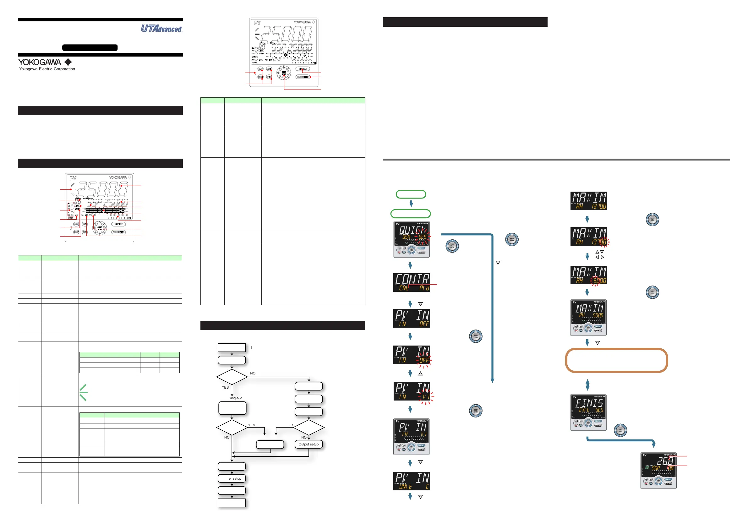
■ Making Settings Using Quick Setting Function
Example: Setting to PID control, thermocouple type K (range of 0.0 to
500.0
0
C), and current control output
Forthe detailed procedureand switchingof displays, see"Flow ofQuickSetting
Function"below.Fortheparameterstoset,seethenextpage.
(1)PresstheSET/ENTERkeywhileYESforQSM(Quicksettingmode)isdisplayed.
(2)Setthecontroltypeparameter(CNT)toPID(PIDcontrol).
(3)SetthePVinputtypeparameter(IN)toK1(-270.0to1370.0
0
C).
(4)SetthePVinputunitparameter(UNIT)toC(DegreeCelsius).
(5)SetthemaximumvalueofPVinputrangeparameter(RH)to500.0.
(6)SettheminimumvalueofPVinputrangeparameter(RL)to0.0.
(7)Settheoutputtypeselectionparameter(OT)toOUTterminals(current).
(8)Finally,EXITisdisplayed.ChangeNOtoYESandpresstheSET/ENTERkeyto
completethesetup.OperationDisplayappears.
■ FlowofQuickSettingFunction
InQuicksettingmode,theparameterguideappearsonPVdisplay.
Thisguidecanbeturnedon/offwiththeMODEkey.
First, the control type parameter
(CNT) is displayed.
Initial value: PID (PID control)
H/C (Heating/cooling control) for
Heating/cooling type unit.
The PV input type
parameter (IN) is
displayed.
Initial value: OFF
OFF blinks.
Blinking allows you to
change the setting.
K1 is displayed.
K1 has been registered.
The last digit of the upper limit value blinks.
The parameter RH (maximum
value of PV input range) has been
changed to 500.0.
The setpoint for the parameter
RH has been registered.
The PV input unit parameter
(UNIT) is displayed.
Initial value: C (Degree
Celsius)
Press the SET/ENTER key
while YES is displayed to start
the Quick setting.
Select NO with the Down
arrow key and press the
SET/ENTER key.
Select NO to return to
the Operation Display.
Press the Down arrow key.
Press the Down arrow key.
Press the Down arrow key.
Press the Down arrow key.
Press the SET/ENTER key.
Press the SET/ENTER key.
Press the SET/ENTER key.
Press the SET/ENTER key.
Press the Up arrow key.
The upper limit value of the
setting range is displayed for the
parameter RH (maximum value
of PV input range).
Change the setpoint using the Up/Down
arrow keys to increase and decrease the
value and the Left/Right arrow keys to
move between digits.
Finally, EXIT is displayed.
Press the SET/ENTER key to swtich to the setting mode.
Change NO to YES and press the SET/ENTER key to
complete the setup of the basic function.
Operation Display appears.
The Quick setting function continues in the NO state.
Displays the measured
input value (PV).
Displays the starting
target setpoint (SSP).
Follow the same procedure to set RL to 0.0 and
OT to 00.02.
Set other parameters as needed.
Quick setting starts
Power-on
1.
2.
3.
4.
5.
6.
8.
9.
10.
11.
12.
7.
[YES]
Operation Display
[NO]

 Loading...


