1-1
IM WT310E-02EN
Component Names and Functions
1
1.1 Front Panel, Rear Panel, and Top Panel
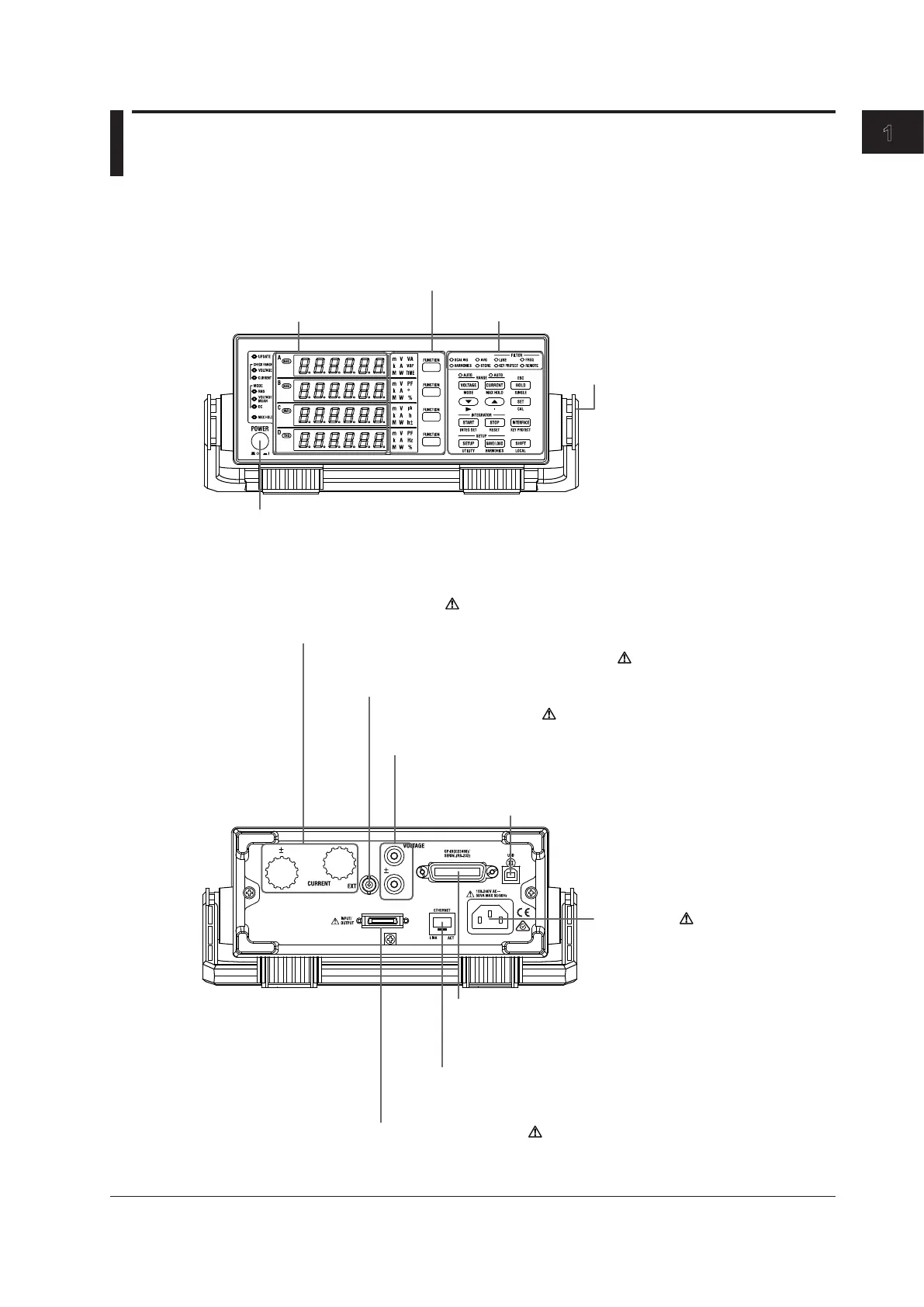
WT310E/WT310EH
Front Panel
Power switch
→ section 2.4
Handle
Used to carry this instrument
→ section 2.1
7-segment LED
display
→ section 1.2
Function and unit indicators
→ section 1.2
Keys
→ section 1.4
Rear Panel
Power inlet
Power connection → section 2.3
GP-IB or RS-232 connector
Used to communicate with this instrument through the GP-IB
or RS-232 interface
→ Communication Interface User’s Manual
External I/O connector
For connecting D/A output and remote control cables
→ chapter 5
For connecting voltage measurement cables
→ sections 2.8 to 2.11
Voltage input terminals
For connecting current measurement
cables → sections 2.8, 2.9, and 2.11
External current sensor input terminal
For connecting cables from an external current sensor
→ section 2.10
Ethernet port
Used to connect this instrument to a network
→ Communication Interface User’s Manual
USB port for PCs
Used to connect this instrument
to a PC that has a USB port
→ Communication Interface User’s Manual
Chapter 1 Component Names and Functions

 Loading...


