2-19
IM WT310E-02EN
Making Preparations for Measurements
2
2.7 Wiring for Accurately Measuring a Single-
phase Device
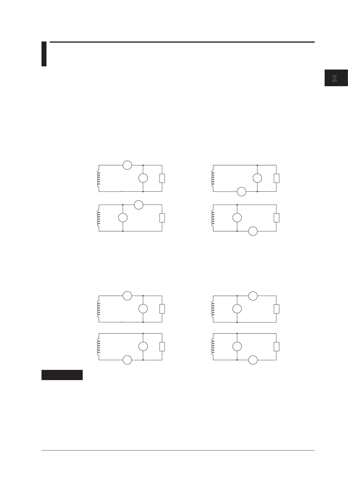
When you are wiring a single-phase device, there are the four patterns of terminal wiring positions
shown in the following figures for wiring the voltage input and current input terminals. Depending on
the terminal wiring positions, the effects of stray capacitance and the effects of the measured voltage
and current amplitudes may become large. To make accurate measurements, refer to the items below
when wiring the voltage input and current input terminals.
Effects of Stray Capacitance
When you are measuring the power of a single-phase device, you can minimize the effects of stray
capacitance on measurement accuracy by connecting the instrument’s current input terminal to the
side that is closest to the earth potential of the power supply (SOURCE).
SOURCE
U
I
C
V
LOAD
U
V
I
C
SOURCE
• Easily affected • Not easily affected
SOURCE
U
I
C
V
LOAD
U
I
C
V
±
±
±
±
±
±
±
±
Effects of the Measured Voltage and Current Amplitudes
SOURCE
U
I
C
V
LOAD
U
I
C
V
• When the measured current is
relatively large
Connect the voltage input terminal
between the current input terminal
and the load.
• When the measured current is
relatively small
Connect the current input terminal
between the voltage input terminal
and the load.
LOAD
U
V
I
C
SOURCE
U
I
C
V
±
±
±
±
±
±
±
±
Explanation
For details on the effects of stray capacitance and the effects of the measured voltage and current
amplitudes, see appendix 1, “How to Make Accurate Measurements.”

 Loading...


