036-21528-007-A-1205
16 Unitary Products Group
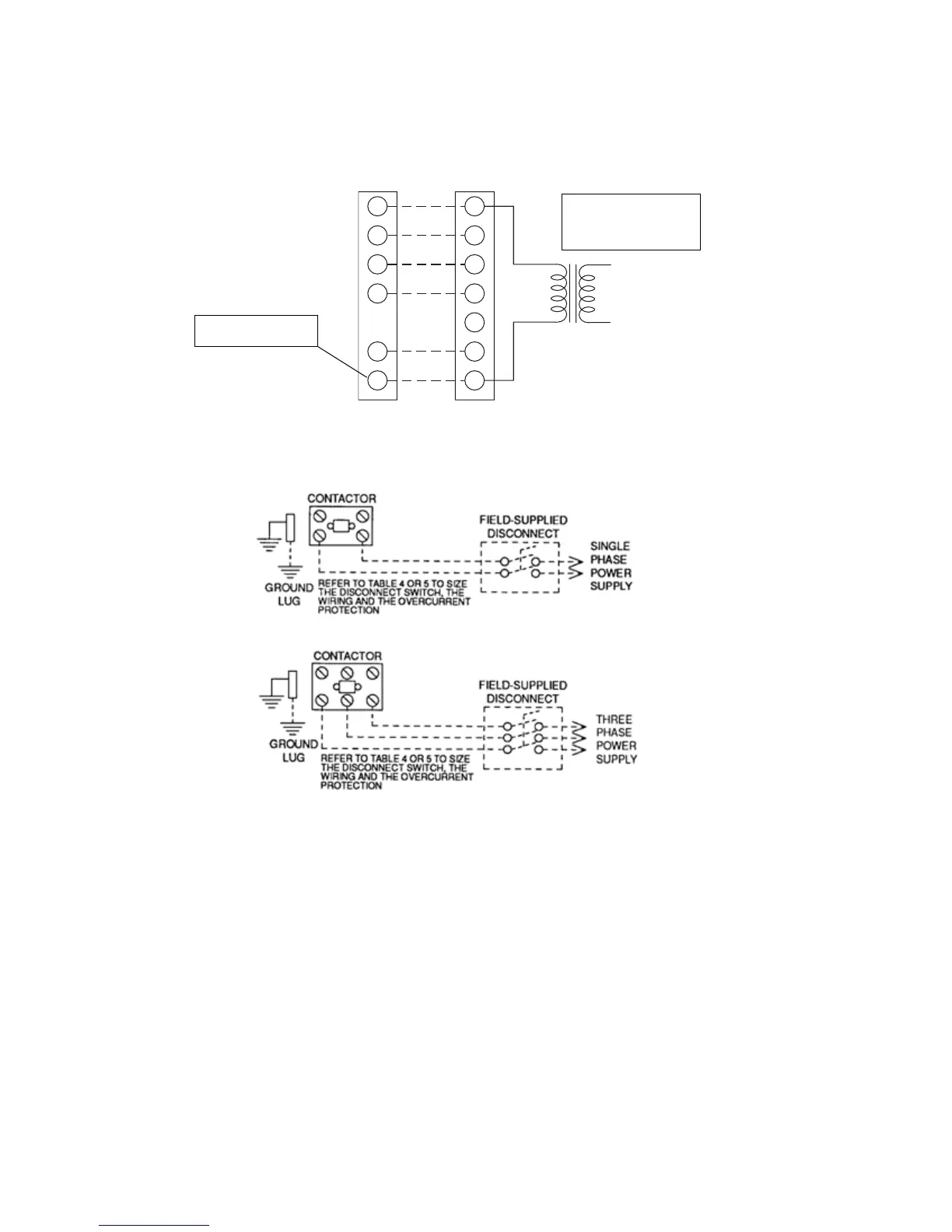
FIGURE 2 - FIELD WIRING DIAGRAM
R
G
W
R
C
YY
W2
C
W1
O O
G
THERMOSTAT UNIT TERMINAL STRIP
*
**
** = Minimum wire size of 18 AWG
wire should be used for all field
installed 24 volt wire.
* = Only required on units with
supplemental electric heat.
PROGRAMMABLE
THERMOSTAT ONLY
24 VOLT TRANSFORMER
Label all wires prior to disconnection when servicing controls. Wiring errors can
cause improper and dangerous operation. Verify proper operation after servicing.
CAUTION:
NOTE:
HEAT ANTICIPATOR
SHOULD BE SET AT 0.25
AMPS FOR ALL MODELS