5-26
SM-18001-rev.1
EXTERNAL INPUT/OUTPUT AND FUNCTION SETTING
(22) Thermistor of Wired Controller (C8)
Thisfunctionisutilizedtocontroltheunitbythebuilt-inthermistorofthewiredcontroller(wired
controllerthermistor)insteadoftheinletairthermistor.
Setthisfunctionat“01”or“02”whenutilizingthisfunction.
However,evenifthisfunctionissetat“01”or“02”,ifthedetectingtemperatureisabnormalduetothe
failureofthethermistorofthewiredcontroller,etc.,thecontrolischangedtotheinletairthermistorof
theindoorunitautomatically.
TheoptionalpartRemoteSensor(THM-R2A)willcontroltheunitwhenitisconnected.
(30) Power Supply ON/OFF 1 (Automatic Operation when Power Supply Is ON) (d1)
Thisfunctionisutilizedtorun/stoptheunitbyturningON/OFFthepowersupply.
Whenthisfunctionisutilizedintheconditionthatthereisnopersontooperatetheunit,monitorthe
systemforpotentialunitfailure.
NOTE:
TheunitisstoppedevenwhenthepowersupplyisturnedON/OFFduetopowerfailure.Ifpower
failureoccursduringthestoppageoftheunit,theoperationisrestartedafterthepowersupplyis
restored.
(31) Not Prepared (d2)
SelectedThermistor SettingCondition ControlledIndoorTemp.
ThermistorofWiredController
00 IndoorSuctionThermistor
01 ThermistorofWiredController
02
AverageValueofIndoorSuctionThermistorand
ThermistorofWiredController
RemoteSensor
00
AverageValueofIndoorSuctionThermistorand
RemoteSensor
01 RemoteSensor
02 Sameas"00"
(26) Not Prepared (CC)
(27) Not Prepared (Cd)
(28) Not Prepared (CE)
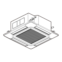
(29) Change of Louver Swing Angle (CF)
Thisfunctionisutilizedtothechangelouverswingangle.
Setting
Condition
LouverSwingAngle
(AirDischargeAngle)
Purpose
00 7 Steps Standard Operation
01 Lower2StepsareCut DraftPrevention
02 Higher2StepsareCut ForHighCeiling
NOTE:
Whenchangingthesetting,turnOFFthepowersupplyor
allowthelouvertomakeonecompleteswingfullyintheauto
swingmodetovalidatethesetting.
Setting
Condition
Logic of
Contact
Sequence
Activation
00 A Contact Normal
Forced
Stoppage
01 B Contact Normal
Forced
Stoppage
Contact "Close"Contact "Open"
Indoor
PCB
Indoor
PCB
ir
(23) Not Prepared (C9)
(24) Not Prepared (CA)
(25) Selection of Forced Stoppage Logic (Cb)
Thisfunctionisutilizedtoselectthelogicofthecontactforforcedstoppagesignalinput.
Thesettingconditionandthelogicofthecontactareasshownbelow.
 Loading...