29
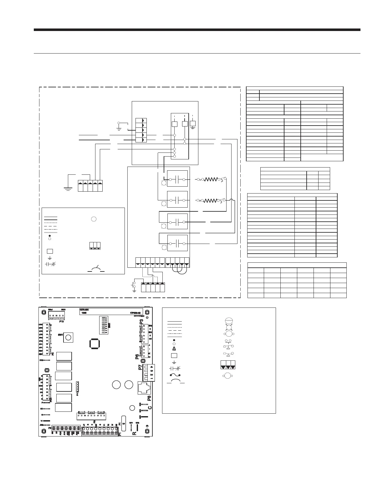
Wiring Schematics cont.
Aurora BASE with 5-Speed ECM cont.
With optional EA Series 10kW Auxiliary Electric Heat Shown
2 – When Aux il iary Heat is inst alle d the BLK/WHT
wire from CC-L1 to PB2-2 and the GRY/WHT wire
from CC-L2 t o PB2-1 must be removed (locat ed in
the heat pump cont rol box ).
1 - Use copper o r aluminum conductors.
3 – Jumpers wires are Factory Installed, and are
Required for auxiliary heat operation.
4 – Low voltage wiring CLASS 2.
Violet
Blue
2
3
Black
Gray
Black
Gray
Green
P9
K1
K2
NO
NO
Brown
Orange
5
4
EA Seri es PCB
P2
1
L2
L1
G
208-230/60/1
Green
P112 3 4 51
C1234
P3 on Aurora ABC Board
P3
EH2CEH1
C
CO
Condensate
Brown
Orange
P1
412
3
C
G
G
To PB2
TB
K4
NO
G
K3
NO
G
Gray
Gray
Black
Black
Black
Gray
NOTE 3
Connects to variable
speed E CM motor only
HE1
TS1
HE2 TS2
Light emi tt ing diode - Green
Polarized connector
Factory Low volt age wi ri ng
Factory Line vol tage wiring
Field l ow volt age wiring
Field l ine volt age wi ring
Optional block
DC Voltage PCB traces
Internal junction
Qui ck c onnect terminal
Thermal Limit Switch
Field wi re lug
Ground
HE -
PB -
Heater element
Power block
Legend
N.O., N.C.
G
L1
Breaker
1 2 3
P
TS
Electric Heat RelayK*
Fused BackupFB
FB1
FB2
AURORA BASE
CONTROL™
Therm istor
Light emitting diode - Green
Relay coil
Switch - Condensate overflow
Switch - High pressure
Switch - Low pressure
Polarized connector
Factory Low voltage wiring
Factory Line voltage wiring
Field l ow volt age wiring
Field l ine volt age wi ring
Optional block
DC Voltage PCB traces
Junction
Qui ck c onnect terminal
Wire nut
Fi eld wi re lug
Ground
Fus e
CC -
CO -
F1 -
FP1 -
HPS -
LPS -
PB1, PB2 -
RV -
SW1 -
SW2 -
TS -
Compres sor Cont actor
Condensate overflow sensor
Fus e
Water Coil Limit Sens or
High pressure switch
Low pressure switch
Power blocks
Rev ersi ng V alve c oil
TEST MODE ABC Board
DIP package 8 position ABC Board
Thermal limit switch
Legend
Relay Con tacts-
N.O., N.C.
G
T
132
P
L1
HWL -
Hot water limit sensor
CS - Compressor Solenoi d
Breaker
208/240V Electric Heat Relay coil
Electric Heat Con tactor
HE - Heater element
ER1 t o ER4 - A ux heat stage relays
EHC -
EHC
Auro ra LED Flash Codes
Sta tus LED (LED3, Green)
Status LE D (LED1, Green)
Conf iguration LED (LED2, Yellow)
Fault LED (LED3, Red)
Rand om St art Del ay ( Alt er n at in g Co lo rs)
Fas t Fl ash
Fas t Fl ash
Fas t Fl ash
1 sec ond on and 1 s econd off
100 milliseconds on and 100 milliseconds off
100 millis econds on and 400 millisec onds of f wit h a 2 s econd pause before repeating
Slow Flash
Fast Flash
Flash Code
Normal Mode
Control is Non-Funct ional
Test Mode
Lockout Active
Dehumidification Mode
Fut ure U se
Fut ure U se
Load Shed
ESD
OF F
ON
Slow F lash
Fas t Fl ash
Flash Code 2
Flash Code 3
Flash Code 6
Flash Code 4
Flash Code 5
Future Use Flash Code 7
Configuration LED (LED2, Yellow)
No Software Overide
OF F
DIP Switch O ver ide Slow F lash
Fault LED (LED1, Red)
Normal Mode
Input Fault Lockout
High Pressure Lockout
Low Pressure Lockout
Fut ure Us e
Freeze De tecti on – FP1
Reserved
Condensate Overflow Lockout
Over/Under Voltage Shut down
Fut ure Us e
Fut ure Us e
FP1 Sensor Error
Flash Code 1
OF F
Flash Code 2
Flash Code 3
Flash Code 4
Flash Code 5
Flash Code 8
Flash Code 6
Flash Code 7
Flash Code 9
Flash Code 10
Flash Code 11
Event
Normal Mode Test Mode
Random Start Delay
Compress or O n Delay
Compressor Minimum On Time
Compress or Short Cycle Delay
Blower Off Delay
Fault Recognition Delay – High Pressure
Start-Up Bypass – Low Pressure
Fault Recognition Delay – Low Pressure
Start-Up Bypass – Low Water Coil Limi t
Fault Recognitio n Delay – Low Water Coil Limit
Fault Recognition Delay – Condensate Overflow
Thermos tat Call Recognit ion T ime
Comfort Alert Recogniti on Time
Auxiliary Heat Stagi ng Del ay
Emergency Heat S tagi ng Dela y
Water Valve Slow Open Delay
Less than 1 sec ond
5 to 80 seconds 1 second
5 seconds < 1 second
30 seconds 2 seconds
Less than 1 sec ond
2 minutes 5 seconds
4 minutes 15 seconds
2 minutes
2 minutes
30 seconds
30 seconds 30 seconds
30 seconds
30 seconds
30 seconds
30 seconds
30 seconds
2 seconds 2 seconds
90 seconds 90 seconds
90 seconds 90 seconds
5 minutes
2 minutes
20 seconds
7.5 seconds
Aurora T iming Events
DESCRIPTION SW2-4 SW2-5
Cycle with Blower ON ON
Cycle with Compressor OFF OFF
Water Valve Slow Opening ON OFF
Cycle with Comm. T-stat Hum Cmd OFF ON
ABC SW2 Accessory Relay
Model TAP-1 TAP-2 TAP-3 TAP-4 TAP-5
024 BLUE R ED TAN GRAY
036 BLUE R ED TAN GRAY
048 BLUE R ED TAN GRAY
060 BLUE R ED TAN GRAY
072 BLUE R ED TAN GRAY
5 SPEED ECM MOTOR LOW VOLTAGE CONNECTIONS
LX SERIES INSTALLATION MANUAL
 Loading...