31
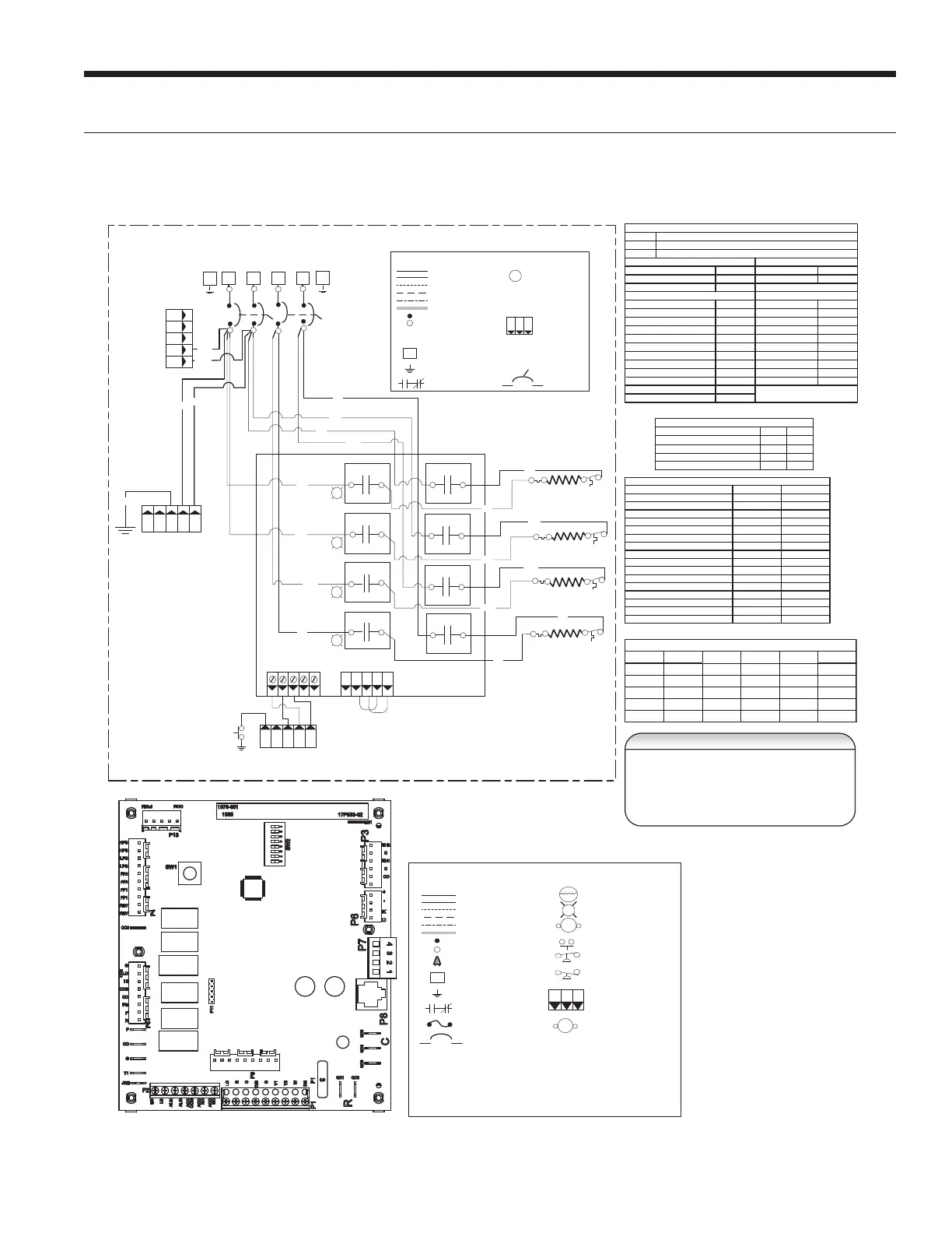
Wiring Schematics cont.
Aurora BASE with 5 Speed ECM and IntelliStart
2
3
P9
5
4
1
L2 L1 L2 L1
Green
P112 3 4 51
Violet
Blue
Brown
Orange
HE1
TS 1
HE3
TS3
HE2
TS2
HE4
TS4
Connects to variable
speed E CM motor only
60 AMP
BR K1
60 AMP
BR K2
G
G
K1
K2
K3
K4
NO
NO
NO
NO
EA Series
PCB
P2
412
3
C
G
G
G
G
K5
NO
K6
NO
K7
NO
K8
NO
Gray
Yellow
Gray
Yellow
Black
Pink
Black
Pink
Pink
Pink
Gray
Black
Yellow
Gray
Black
Yellow
412
3
C
P1
COM
COM
COM
COM
COM
COM
COM
COM
Aux heat staging
FB1
FB2
FB3
FB4
P3 on Aurora ABC Board
P3
EH2CEH1
C
CO
Light emitting diode - Green
Polarized connector
Factory Low volt age wi ri ng
Factory Line voltage wiring
Fi eld l ow voltage wiring
Fi eld l ine volt age wi ring
Optional block
DC Voltage PCB traces
Internal junction
Qui ck c onnect terminal
Thermal Limi t Switch
Fi eld wi re lug
Ground
HE -
PB -
Heater element
Power block
Legend
N.O., N.C.
G
L1
Breaker
1 2 3
P
TS
Electric Heat RelayK*
Fused BackupFB
2 - Use manufact urer’s part number 19P592-01 (jumper
bar assem bly) when si ngle sourc e power is required.
1 - Use copper o r aluminum conductors.
3 – Jumpers wire s are Factory Installed, and are
required for a uxi liary heat operat ion.
4 – Low vol tage wiring CLASS 2.
NOTE 3
With optional EA Series 20kW Auxiliary Electric Heat Shown
AURORA BASE
CONTROL™
Thermistor
Light emitting diode - Green
Relay coil
Switch - Condensate overflow
Switch - High pressure
Switch - Low pressure
Polarized connector
Factory Low voltage wi ring
Factory Line voltage wiring
Fi eld l ow voltage wiring
Fi eld l ine volt age wi ring
Optional block
DC Voltage PCB traces
Junction
Qui ck c onnect terminal
Wire nut
Fi eld wi re lug
Ground
Fus e
CC -
CO -
F1 -
FP1 -
HPS -
LPS -
PB1, PB2 -
RV -
SW1 -
SW2 -
TS -
Compres sor Cont actor
Condensate overflow sensor
Fus e
Water Coil Limit Sensor
High pressure switch
Low pressure switch
Power blocks
Reversi ng Valve coil
TEST MODE ABC Board
DIP package 8 position AB C Board
Thermal limit switch
Legend
Relay Con tacts-
N.O., N.C.
G
T
132
P
L1
HWL -
Hot water limit sensor
CS - Com pressor Solenoi d
Breaker
208/240V Electric Heat Relay coil
E lec tri c H ea t Co n tac tor
HE - Heater element
ER1 t o ER4 - A ux heat stage relays
EHC -
EHC
Notes
1 - Switc h blue a nd r ed wir es for 208V oper ation.
2 - The blk/wh and gray/wh wires are removed when Aux He at is installed
3 - Refer to units X13 MOTOR LOW VOLTAGE CONNECTION table for factory settings.
4 - Wires p rovided for Auxiliary Heat low voltage control. When connected the Auxiliary Heat
powers blower and controls. Wires are secured at blower.
5 - Field installed SPST relay required for dual fuel instal lation.
6 – All low voltage wi ri
ng CLAS S 2
7 – Use c opper o r aluminum conductors
Aur o ra L ED Fl as h Codes
Status LED (LED3, Green)
Status LE D (LED1, Green)
Conf iguration LED (LE D2, Yellow)
Fault LED (LED3, Red)
Random Start Delay (Altern atin g Co lo rs)
Fas t Fl ash
Fas t Fl ash
Fas t Fl ash
1 sec ond on and 1 s econd off
100 milliseconds on and 100 m illiseconds of f
100 milliseconds on and 400 milliseconds of f wit h a 2 second pause before repe ating
Slow Flash
Fast Flash
Flash Code
Normal Mode
Cont rol is Non-Functional
Test Mode
Lockout Active
Dehumidification Mode
Fut ure U se
Fut ure U se
Load Shed
ESD
OF F
ON
Slow Flash
Fas t Fl ash
Flash Code 2
Flash Code 3
Flash Code 6
Flash Code 4
Flash Code 5
Future Use Fl ash Code 7
Configuration LED (LED2, Yellow)
No Software Overide
OF F
DIP Switch Overide Slow Flash
Fau lt LED (LED1, Red)
Normal Mode
Input Fault Lockout
High Pressure Lockout
Low Pressure Lockout
Fut ure U se
Freeze Detection – FP1
Reserved
Condensate Overflow Lockout
Over/Under Voltage Shut down
Fut ure U se
Fut ure U se
FP1 Sensor Error
Flash Code 1
OF F
Flash Code 2
Flash Code 3
Flash Code 4
Flash Code 5
Flash Code 8
Flash Code 6
Flash Code 7
Flash Code 9
Flash Code 10
Flash Code 11
Event
Normal Mode Test Mode
Random Start Delay
Compress or On Delay
Compressor Minimum On Time
Compressor S hort Cycl e Delay
Blower Of f Delay
Fault Recognition Delay – High Pressure
Start-Up Bypass – Low Pressure
Fault Recognition Delay – Low Pressure
Start-Up Bypass – Low Water Coil Limit
Fault Recogn ition Delay – Low Water Coil Limit
Fault Recogn ition Delay – Condensate Overflow
Thermos tat Call Rec ognit ion Tim e
Comfort Alert Recog nition Time
Auxi liary Heat Stagi ng Delay
Emergency Heat S tagi ng Dela y
Water Valve S low Open Delay
Less than 1 sec ond
5 to 80 seconds 1 second
5 seconds < 1 second
30 seconds 2 seconds
Less than 1 second
2 minutes 5 seconds
4 minutes 15 seconds
2 minutes
2 minutes
30 seconds
30 seconds 30 seconds
30 seconds
30 seconds
30 seconds
30 seconds
30 seconds
2 seconds 2 seconds
90 seconds 90 seconds
90 seconds 90 seconds
5 minutes
2 minutes
20 seconds
7.5 seconds
Aurora T imi ng Events
DESCRIPTION SW2-4 SW2-5
Cycle with Blower ON ON
Cycle with Compressor OFF OFF
Water Valve Slow Opening ON OFF
Cycle with Comm. T-stat Hum Cmd OFF ON
ABC SW2 Accessory Relay
Model TAP-1 TAP-2 TAP-3 TAP-4 TAP-5
024 BLUE R ED T AN GRAY
036 BLUE R ED T AN GRAY
048 BLUE R ED T AN GRAY
060 BLUE R ED T AN GRAY
072 BLUE RED TAN GRAY
5 SPEED ECM MOTOR LOW VOLTAGE CONNECTIONS
LX SERIES INSTALLATION MANUAL
 Loading...