JOHNSON CONTROLS
6
FORM 160.69-N3
ISSUE DATE: 10/30/2015
LIST OF FIGURES
LIST OF TABLES
FIGURE 1 - YD Form 2 Rigging ..............................................................................................................................10
FIGURE 2 - Neoprene Isolators Dimensions (Inches)............................................................................................. 11
FIGURE 3 - Neoprene Isolators Dimensions (mm) ................................................................................................. 11
FIGURE 4 - Neoprene Isolators Dimensions (Inches).............................................................................................12
FIGURE 5 - Neoprene Isolators Dimensions (mm) .................................................................................................12
FIGURE 6 - Neoprene Isolators Dimensions (Inches).............................................................................................13
FIGURE 7 - Neoprene Isolators Dimensions (mm) .................................................................................................13
FIGURE 8 - Spring Isolators ....................................................................................................................................14
FIGURE 9 - Schematic of a Typical Piping Arrangement ........................................................................................ 16
FIGURE 10 - Typical Refrigerant Vent Piping ..........................................................................................................18
FIGURE 11 - Control Panel Positioning...................................................................................................................19
FIGURE 12 - Compressor Motor Field Connections Diagram (EMS Application) ................................................... 20
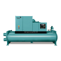
FIGURE 13 - Model YD Chiller ................................................................................................................................ 21
FIGURE 14 - Dimensions – K Compressor Units Ft.–In. (mm) ...............................................................................22
TABLE 1 - Dimensions – K Compressor Units Ft.–In.(mm) ....................................................................................23
TABLE 2 - Approximate Unit Weight Including Motor* — English (Metric) .............................................................24
TABLE 3 - Marine Waterbox Weight — English (Metric) .........................................................................................24
TABLE 4 - Approximate Unit Motor Weights — English (Metric) ............................................................................25
TABLE 5 - SI Metric Conversion .............................................................................................................................27
* Refer to product drawings for detailed weight information
 Loading...
