22
P5417090
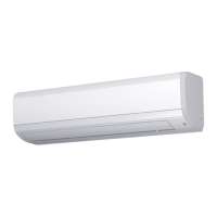
(1) Standard condensate connection is on the rear of the unit, viewed from the discharge grilles. The
condensate connection can also be connected to the left side of the unit.
Refer to Section 5.2.6 for details.
7. Condensate Piping
Donotruncondensatepipingintoundergroundareasnearsanitaryorsewagelineswheretoxic
andcorrosivegascanseepintothesystem.Thiscreatesapathwayfortheowofpoisonousgasto
penetrate inhabited areas.
Unit: Inch (mm)
MBH
Dimension
6 and 8 12 15 to 30
A 25-1/8 (638) 25-7/8 (657) 36-7/16 (925)
B 22-3/8 (568) 22-3/8 (568) 21-5/8 (550)
C 1-3/4 (45) 1-3/4 (45) 2 (51)
D 4-3/16 (107) 4-3/16 (107) 4-3/4 (120)
E 2-9/16 (65) 2-9/16 (65) 3-1/8 (80)
View from Front Side for Indoor Unit
(VP16)
ɸ E
Exterior Contour for Indoor Unit
Hole for
Rear Piping
Condensate Piping Connection
A
B
C
D
Hole for Rear Piping
C
ɸ E
● Check to ensure that the condensate piping discharges moisture properly. If connected incorrectly, it can
cause structural damage to indoor wall and ceiling surfaces, and damage to furniture and carpeting.
● Avoid sloping the condensate piping upward as it will impede drainage. Moisture will settle back into the
unit and may cause water leakage when unit operation stops.
● Do not connect condensation drainage with sanitary or sewer lines or any other condensate piping.
● When the main condensate piping is connected with other indoor units, the connected position of each
indoor unit must be higher than the main pipe. The pipe size of the main condensate piping must be large
enough according to the unit size and number of units.
● After performing condensate piping work and electrical wiring, check to ensure that water outow is as
smooth as in the following procedure.
● In order to properly drain condensate water, mount the indoor unit on a slight incline to the condensate
piping connection side. (Installed 1/16 to 1/8 inch (2 to 3mm) relative to the unit level.)
● When the left side piping is selected, the condensate piping outlet should be on the left side.
If it is not on the left side, and the mounting plate is secured onto the wall with right down slope, the
condensate could ow back into the unit, causing a leak from the condensate pan.
 Loading...
