Page - 14/100 AE0ZP0EC - AC-0 SSL SENSORED - User Manual
4 Can advantages
The complexity of today systems needs more and more data, signal and
information must flow from a node to another. CAN is the solution to different
problems that arise from this complexity
- simplified design (readily available, multi sourced components and tools)
- lower costs (less and smaller cables )
- improved reliability (fewer connections)
- analysis of problems improved (easy connection with a pc to read the data
flowing through the cable).
4.2.4 Wirings: I/O connections
- After crimping the cable, verify that all strands are entrapped in the wire
barrel.
- Verify that all the crimped contacts are completely inserted on the connector
cavities.
U A cable connected to the wrong pin can lead to short circuits and failure;
so, before turning on the truck for the first time, verify with a multimeter the
continuity between the starting point and the end of a signal wire.
- For information about the mating connector pin assignment see the
paragraph “description of the connectors”.
4.2.5 Connection of the encoder
1) AC-0 card is fit for different types of encoder. To control AC motor with Zapi
inverter, it is necessary to install an incremental encoder with 2 phases
shifted of 90°. The encoder power supply can be +5 or +12 V. It can have
different electronic output.
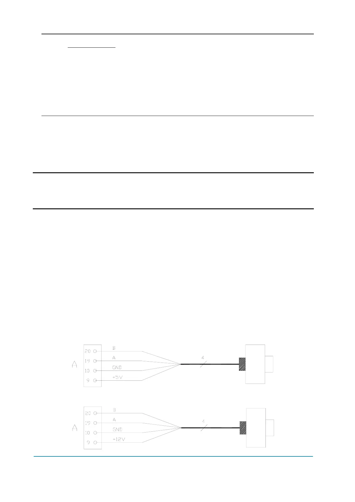
A9 +5V/+12V positive of encoder power supply.
A10 GND negative of encoder power supply.
A19 A phase A of encoder.
A20 B phase B of encoder.
2) Connection of encoder with open collector output; +5 V power supply.
3) Connection of encoder with open collector output: +12 V power supply.