Page - 26/100 AE0ZP0EC - AC-0 SSL SENSORED - User Manual
programming (if used).
C8 FLASH Must be connected to C7 for the Flash memory
programming (if used).
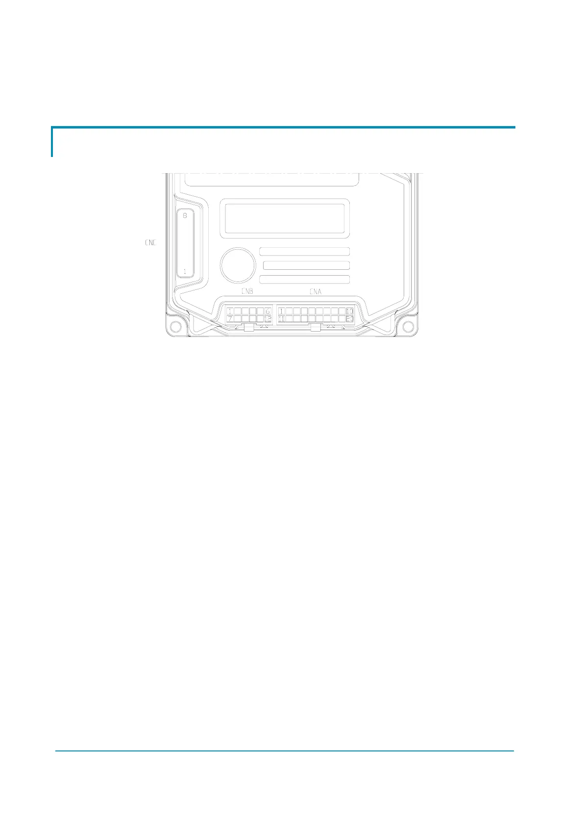
6.2 Connectors of the logic – Pump configuration
Figure 6–4
CNA connector
A1 NMC Negative of main contactor coil.
A2 PMC/PEB Positive of main contactor coil and of the first auxiliary
output.
A3 NAUX 1 Negative of the first auxiliary output.
A4 NAUX 2 Negative of the second auxiliary output.
A5 PPC/PEV Positive of the second and the third auxiliary output.
A6 NAUX 3 Negative of the third auxiliary output.
A7 CAN LOW Low level CAN-BUS voltage I/O.
A8 -BATT -Batt.
A9 ENC + Encoder Positive Supply (+5 or +12 Vdc).
A10 ENC - Encoder Negative Supply (GND to minus battery).
A11 HM (+B) This output provides a +Batt for general-purpose
applications; 3 A maximum current.
A12 -BATT -Batt.
A13 MOT TH Motor thermal sensor input. The internal pull-up is a
fixed 2 mA (Max 5 V) source current.
A14 SPEED 3 Input for third speed request; it is active high.
A15 SPEED 2 Input for second speed request; it is active high.
A16 +12V This output provides a +12 V signal for the MDI PRC;
100 mA maximum current.
A17 CAN HIGH High level CAN-BUS voltage I/O.
A18 CPOTB Proportional electrovalves potentiometer wiper.
A19 ENC A Encoder Channel A.