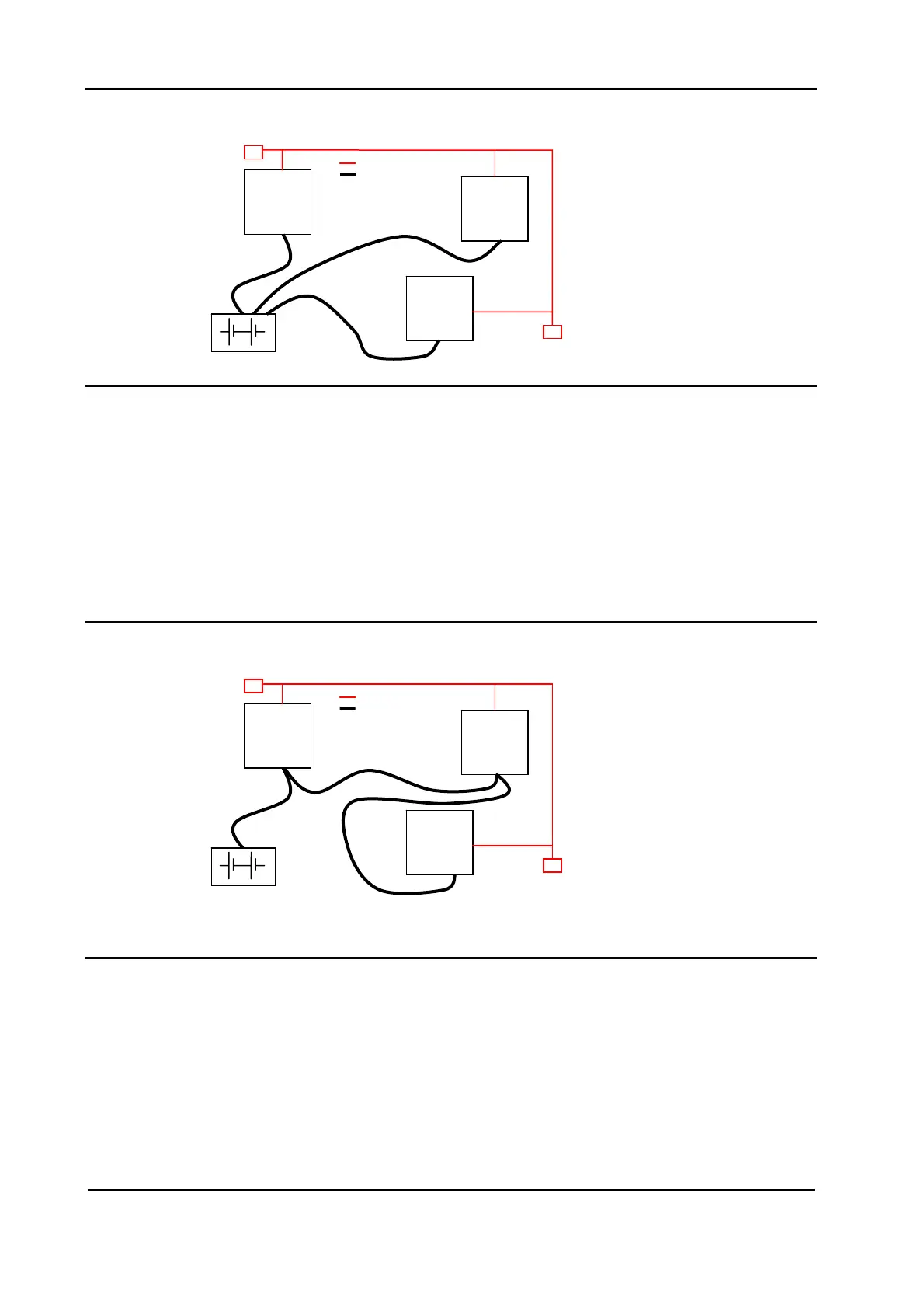
U Wrong Layout:
The red lines are can wires.
ample traction controller, pump The black boxes are different modules, for ex
nbus. controller and display connected by ca
he black lines are the power cables. T
This is apparently a good layout, but can bring to errors in the can line.
olution depends on the type of nodes (modules) connected in the The best s
network.
t in terms of power, then the preferable If the modules are very differen
connection is the daisy chain.
Module
1
Module
2
Module
3
U Correct Layout:
Note: Module 1 power > Module 2 power > Module 3 power
The chain starts from the –BATT post of the controller that works with the
highest current, and the others are connected in a decreasing order of power.
Module
1
Module
2
Module
3
Page - 14/86 AEQZP0BA – COMBI AC1 - User Manual