Section 5. Installation
5-9
Connection to a GE Master II Base/Repeater
For: Zetron Model 37-MAX
To: GE Master II Base/Repeater
Using: 709-7179 Generic Radio Cable
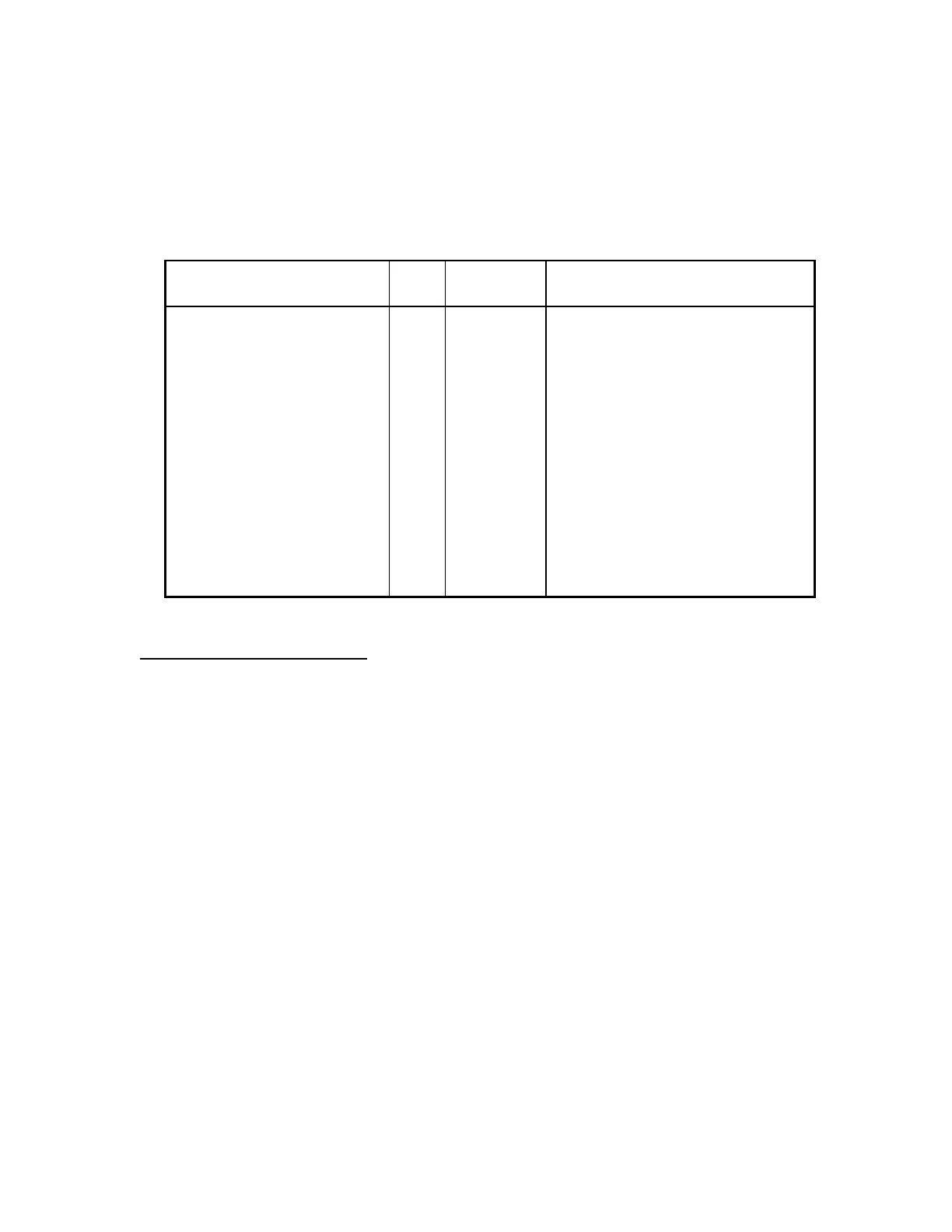
37-MAX End
Function
J1
pin#
Wire
Color
Radio End
Connection/Notes
+12 volts DC 1 RED Station supply +12 volts DC
Ground 2 BLACK Station supply ground
Discriminator Input 3 WHITE J606 on IF/Audio/Squelch board
Ground 4 BRAID No connection
TX Audio Output 5 BLUE J933, pin 6 on old control board,
or P2, pin 4 on new IDA board
Ground (spare) 6 N/C
PTT Output 7 ORANGE J931, pin 14 (Local PTT)
Ground 8 BROWN J933, pin 2 (CG Low)
COR Input 9 YELLOW J932, pin18 (CAS)
CTCSS/DCS Encode 10 GREEN J933, pin 3, (CG Hi)
GE Master II Configuration
Two versions of the GE Master II Repeater Control Panel exist. The "earlier" version is
identified by multiple plug-in cards, the 10 volt regulator card being on the far right. The
"later" version is a single panel (no plug-in cards), and is identified by the local mic
connector, speaker, and volume knob on the front. All connections are the same except for
the TX Audio. On the later models, TX Audio is connected to the "Battery Alarm Audio"
point. Follow these steps:
1. Remove the jumper between H16 and H17 (if installed) on the 10 volt regulator card.
2. Discriminator audio may be connected to Volume Squelch Hi (J932, pin 3).
3. Remove any existing repeater tone panel (card-per-tone), and "Repeater Audio" and/or
"Repeater Control" cards (if installed).
 Loading...