Section 5. Installation
5-11
Connection to a GE EXEC II Base
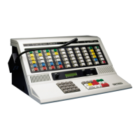
For: Zetron Model 37-MAX
To: GE EXEC II Base
Using: 709-7179 Generic Radio Cable
37-MAX End
Function
J1
pin#
Wire
Color
Radio End
Connection/Notes
+12 volts DC 1 RED H20 (A+)
Ground 2 BLACK Chassis ground
Discriminator Input 3 WHITE J907, pin 8 (Vol Hi)
Ground 4 BRAID No connection
TX Audio Output 5 BLUE H36 (Tone Hi)
Ground (spare) 6 N/C
PTT Output 7 ORANGE J907, pin 10 (PTT)
Ground 8 BROWN Ground trace
COR Input 9 YELLOW J913, pin 4 (CAS)
CTCSS/DCS Encode 10 GREEN J907, pin 6 (CG Hi)
GE EXEC II Configuration
To modify the radio for full-duplex (repeater) operation, follow these steps:
1. Remove Q905 and Q908 on the System Audio Squelch board (SAS board).
2. Install a wire jumper from the Q908 emitter solder pad to the Q908 collector solder pad.
3. Care should be taken not to damage the transmitter PA due to continuous duty operation.


 To Next Page