Section 5. Installation
5-29
Connections to a Uniden ARU-251 Repeater
For: Zetron Model 37-MAX
To: Uniden ARU-251 (This is NOT for the ARU-251K)
Using: 709-7179 Generic Radio Cable
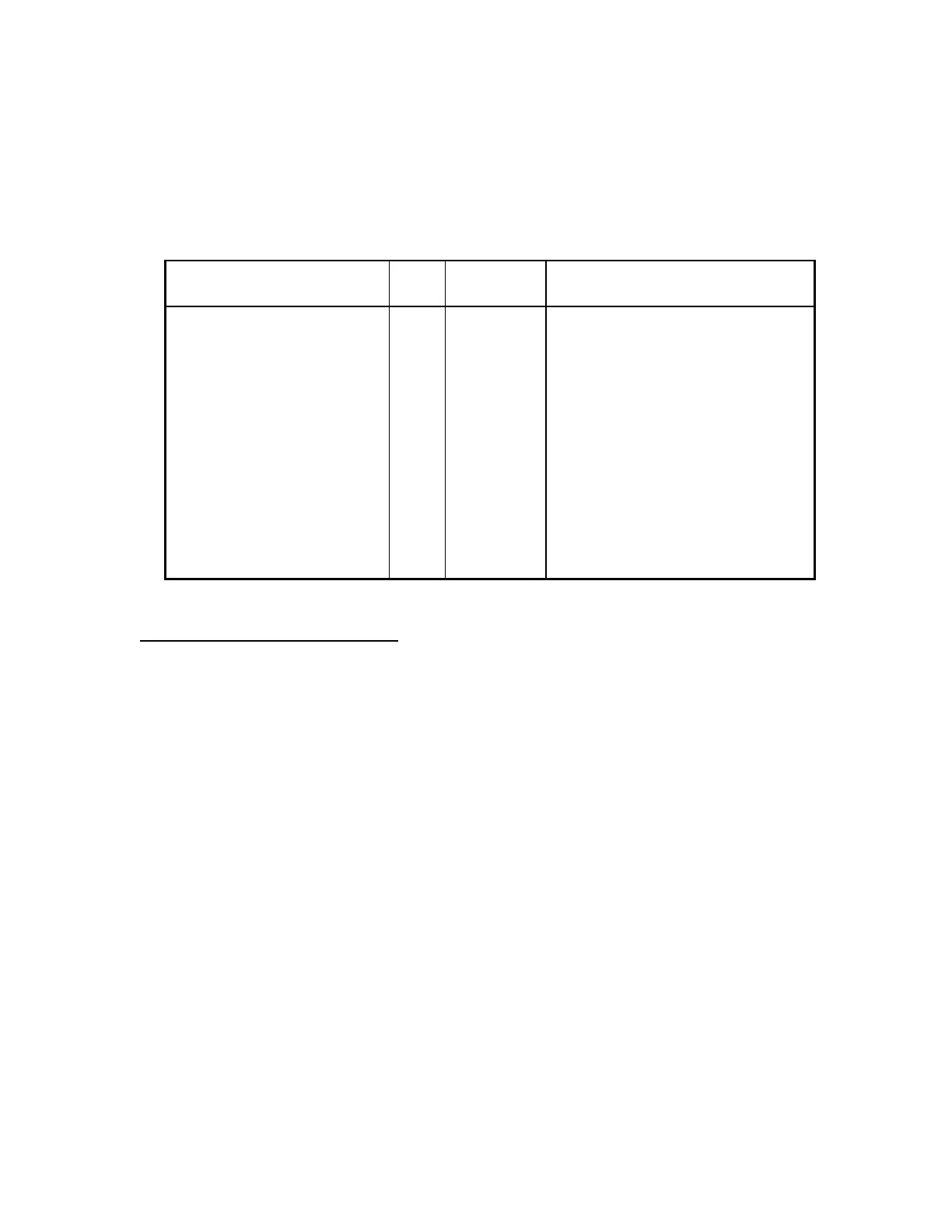
37-MAX End
Function
J1
pin#
Wire
Color
Radio End
Connection/Notes
+12 volts DC 1 RED Pin 4
Ground 2 BLACK Pin 5
Discriminator Input 3 WHITE Pin 1
Ground 4 BRAID No connection
TX Audio Output 5 BLUE Pin 6
Ground (spare) 6 N/C
PTT Output 7 ORANGE Pin 3
Ground 8 BROWN No connection
COR Input 9 YELLOW Pin 2
CTCSS/DCS Encode 10 GREEN Pin 9
Uniden ARU-251 Configuration
1. At the radio's accessory jack, install a jumper wire between pin 7 and pin 8 (Audio Amp
Out to Speaker In).
2. Disconnect the Tone Encode lead from the Exciter at FT18 on the Exciter case, and leave
the wire disconnected.
3. Attach a wire from FT18 on the Exciter case to pin 9 of the accessory jack. This provides
a path for CTCSS encode from the panel to the transmitter exciter.
4. Set the Control Board switch to the Carrier Squelch position.
5. Set the Front Panel switches to Local and Monitor.


 To Next Page