Section 5. Installation
5-17
Connection to a Kenwood TKR720 / TKR820
For: Zetron Model 37-MAX
To: Kenwood TKR720 / TKR820
Using: 709-7179 Generic Radio Cable
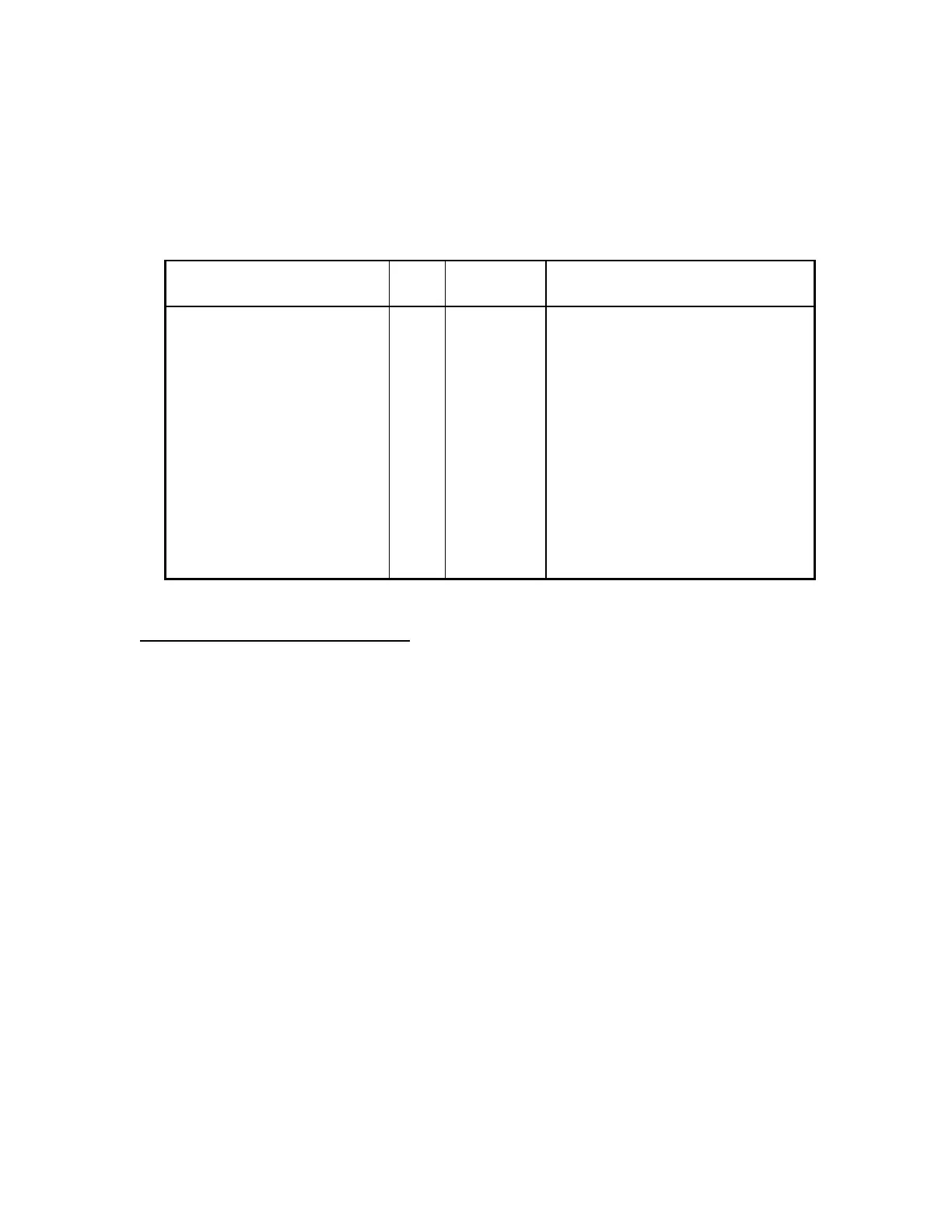
37-MAX End
Function
J1
pin#
Wire
Color
Radio End
Connection/Notes
+12 volts DC 1 RED Pin-7, SB
Ground 2 BLACK Pin-6 and Pin-11, Ground
Discriminator Input 3 WHITE Pin-4, DE
Ground 4 BRAID No connection
TX Audio Output 5 BLUE Pin-5, L1
Ground (spare) 6 N/C
PTT Output 7 ORANGE Pin-8, PTT
Ground 8 BROWN No connection
COR Input 9 YELLOW Pin-13, CO
CTCSS/DCS Encode 10 GREEN Pin3, D1
TKR720 / TKR820 Configuration
For all TKR repeaters:
1. Make up two wire jumpers to install on the radio's auxiliary plug. Place one from pin-1
(HK) to pin-2 (LG), this is the PTT Enable jumper. Place the second from pin-9 (SI) to
pin-12 (SO), this is the Speaker Enable jumper.
2. Set the repeater's front panel switches to: TAKEOVER = Off / Disabled, REPEAT = Off
/ Full Duplex Transceiver, Monitor = DC
NOTE: The following modifications do not apply to all versions of the TKR-repeaters, only the
earlier versions. Refer to the Kenwood service manual and schematic diagrams.
1. On the TX/RX Unit board, foil side: Cut the trace leading to CN3-8 (AFO). Add a jumper wire
between CN3-8 and CN6-9 (DET). This corrects a foil error found in older Kenwood units. Cut
the trace between CN7-1 (tone) and R68. This isolates the tone board injection point when the
Zetron device keys the transmitter.
2. On the Display Unit board, foil side: Remove R14, and add a jumper wire between CN8-4 (DE)
and CN2-6 (DET). This bypasses C22 on the Display Unit board for DCS decode capability.
 Loading...