Section 5. Installation
5-14
Connection to an EF Johnson CR1010
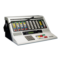
For: Zetron Model 37-MAX
To: EF Johnson CR1010
Using: 709-7179 Generic Radio Cable
37-MAX End
Function
J1
pin#
Wire
Color
Radio End
Connection/Notes
+12 volts DC 1 RED Logic Drawer, pin-15, +13.8 V
Ground 2 BLACK Logic Drawer, pin-13, Ground
Discriminator Input 3 WHITE Logic Drawer, pin-5, CG Audio
Ground 4 BRAID No connection
Ground (spare) 6 N/C
PTT Output 7 ORANGE
Logic Drawer, pin-23,
Ground 8 BROWN Ground
COR Input 9 YELLOW Logic Drawer, pin-19, fast squelch
TX Audio Output 5 BLUE +
56 kΩ
Logic Drawer, pin-18, TX Tone CG
CTCSS/DCS Encode 10 GREEN +
15 k
Ω
Logic Drawer, pin-18, TX Tone CG
CR1010 Configuration
1. Remove the brown wire from receiver going to the exciter transmit audio (pin 1).
2. Add a 10 kΩ resistor across R123 in the exciter.
3. Add a 56 kΩ resistor to the radio end of the blue TX audio wire, and a 15 kΩ to the radio
end of the green CTCSS/DCS encode wire. The other end of both resistors are tied to the
TX Tone CG input on the Logic drawer (pin-18).
NOTE: This configuration does not use the deviation limiter in the exciter. It does provide a
higher quality repeat audio than the alternate hookup that follows this.


 To Next Page