10 AP3/10, AP3/15 Installation Instructions
e. Remove the existing cable and pass the new cable through the
grommet assembly
f. Remake the cable connections and tighten the grommet locknut to
ensure the cable is securely clamped
g. Refasten the cover.
4. All internal wiring is factory mounted and should not be altered or modified.
This appliance must be earthed.
Do not switch on the electrical supply until the water heater is full of water.
Commissioning
1. Check that all the requirements under "Installation Requirements" have
been met.
2. Check that all water and electrical connections are correct and tight
3. Open a hot water tap
4. Open the isolating valve and permit the heater to fill
5. Close the hot tap when water starts to flow from it
6. Check for leaks and rectify as necessary
7. Check the operation of the expansion relief valve and the T&P valve, if fitted.
8. Manually operate Expansion Relief Valve to ensure free water flow through
the discharge pipe by turning the knob to the left and holding in the
open position
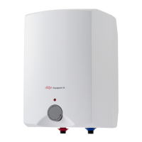
9. Set the temperature control knob to the desired position. The ‘E’ position
with a water temperature of approx. 55ºC is recommended for economical
operation while minimising lime-scale deposits and thermal losses.
Note:
• Rotating the temperature control knob varies the water temperature
over the range 7ºC to 75ºC
• Hot water at 55ºC or more can scald
• The ‘*’ position provides frost protection while the heater is connected
to power.
10. Switch on the electrical supply to the unit. The red neon light will glow
during the heating cycle and will extinguish when the selected temperature
is reached until the next heating cycle.
11. During the heating cycle no water should escape to waste from either the
expansion relief or T&P relief valves.
 Loading...
