Page 7 of 12 Zip Hydroboil - Installation & Operating Instructions - 81447 - April 2013 v1.03
Installation Procedures Continued
Approximate Weights When Filled
10Litremodels 29.5kg
15Litremodels 34.5kg
25Litremodels 47.0kg
40Litremodels 71.0kg
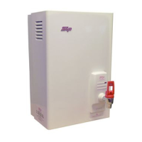
250mm
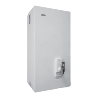
Wiring
Concealed
Vent
Concealed
Inlet
45mm
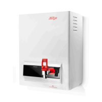
Fig. b
Fig. a
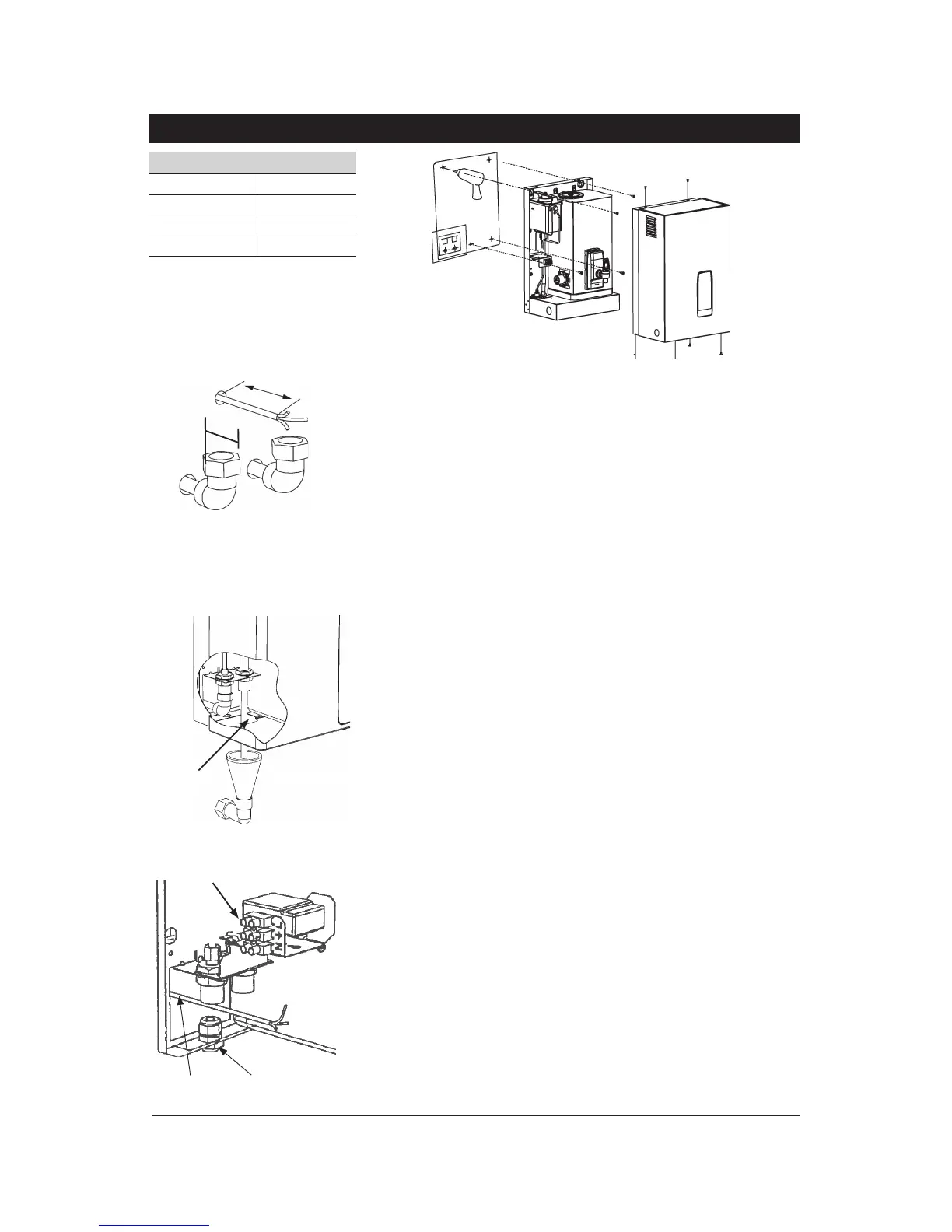
VisibleTundishVentline
Surfacemount
cable entry
TerminalBlock
Concealed
cable entry
Step 3 – Connecting
a) Plumbing
Forexposedplumbingconnection,connectthecoldwaterinletpipefromthebase
oftheheaterdirectlytothe15mmorinchBSPcompressionfittings.
Forconcealedplumbingconnections,connectthecoldwaterpipethroughtherear
ofthechassisusinga15mmorinchBSPcapillaryelbow.
Coldwaterpipesmustbeflushedbeforeconnectiontotheinlet.Anycloggingdue
tosedimentorfineswilladverselyaffecttheoperationoftheheater.
Itisrecommendedthattheheaterbeinstalledwithaisolatingvalvewhichallows
ittobeisolatedfromthemainssupplyforservicing.
Water pressure requirements:
Minimum-0.07MPa(0.7bar)Maximum-0.7MPa(7bar).
Caution:Ifpressureislikelytoexceed0.7MPa(7bar),apressurelimitingvalvemust
beinstalledinthecoldwatersupplyline.Ziprecommendsavalveratedat3.5bar
(0.35MPa)forthisapplication(ZippartNo.AQ3).
b) Venting
Aventatthebaseoftheheatermustbeplumbedtoasafevisiblelocationas,
undercertainconditions,itmaydischargecoldorboilingwaterand/orsteam.
Forexposedventplumbing,connectventoutletfromthebaseofheatertoa
15mmorhalfinchODpipewhichhasacontinuousfall,isnomorethan3metres
long,hasnomorethan3rightanglebends,anddischargestoawastewater
drain.
Forconcealedventplumbing(Fig.a),connectplumbingtotheventoutletfromthe
heaterrearusingacapillaryelbowprotruding45mmfromthewall.Theplumbing
mustthenbedirectedtoatundishthatmustbeinavisiblelocationbeforebeing
plumbedawaytowaste.
Alternativelyattachthetundishtothewall(Fig.b)andplumbawaytowaste.
c) Electrical
Forconcealedelectricalconnection,connectapowercablefromtherearofthe
heatertotheterminalblockwithintheheaterasshown.
Forsurfacemountinstallationrunthepowercablethroughthecableentryglandat
thebottomoftheunittotheterminalblockwithintheheater.Ensurethecableis
firmlysecured.
Isolationswitchesmusthaveacontactseparationofatleast3mminallpoles.
Do not turn the power ONuntilwaterflowsfromthetap.