14
INSTALLATION INSTRUCTIONS & USER MANUAL
210006 V2.00 SEPT 2017 - ZIP VPII/103-153(UB)
TECHNICAL SUPPORT TEL: 0345 6 005 005 EMAIL: SERVICE@ZIPINDUSTRIES .CO.UK
WWW.ZIPWATER.CO.UK
• Check that all Installation requirements have been met.
• Check that all water and electrical connections are correct and tight.
• Open a hot water tap.
• Open the water mains isolating valve and allow the heater to fill.
• Close the hot water tap when water starts to flow from it.(The heater vessel should now
be full).
• Check for leaks and rectify as necessary.
• Manually operate the Expansion Relief Valve and T&P Valve if fitted to ensure free water
flow through the discharge pipe by turning the knob to the left and holding it in the open
position.
• Set the temperature control knob to the required position. The factory set position
as delivered will maintain the most economical stored water temperature at approx.
35ºC. Lime-scale formation and heat loss are minimised at this setting, however the
operating temperature may be increased as required to a maximum of 80ºC.
COMMISSIONING AND OPERATION
Fig.4
This setting protects the appliance against frost damage,
but this protection does not extend to the connecting
pipework and fittings.
NB.The water heater cannot be switched off via the temperature selector.
It can only be switched off at the isolating switched mains supply socket.
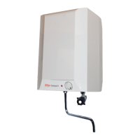
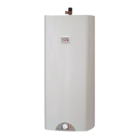
ZIP Varipoint II
Fig.3
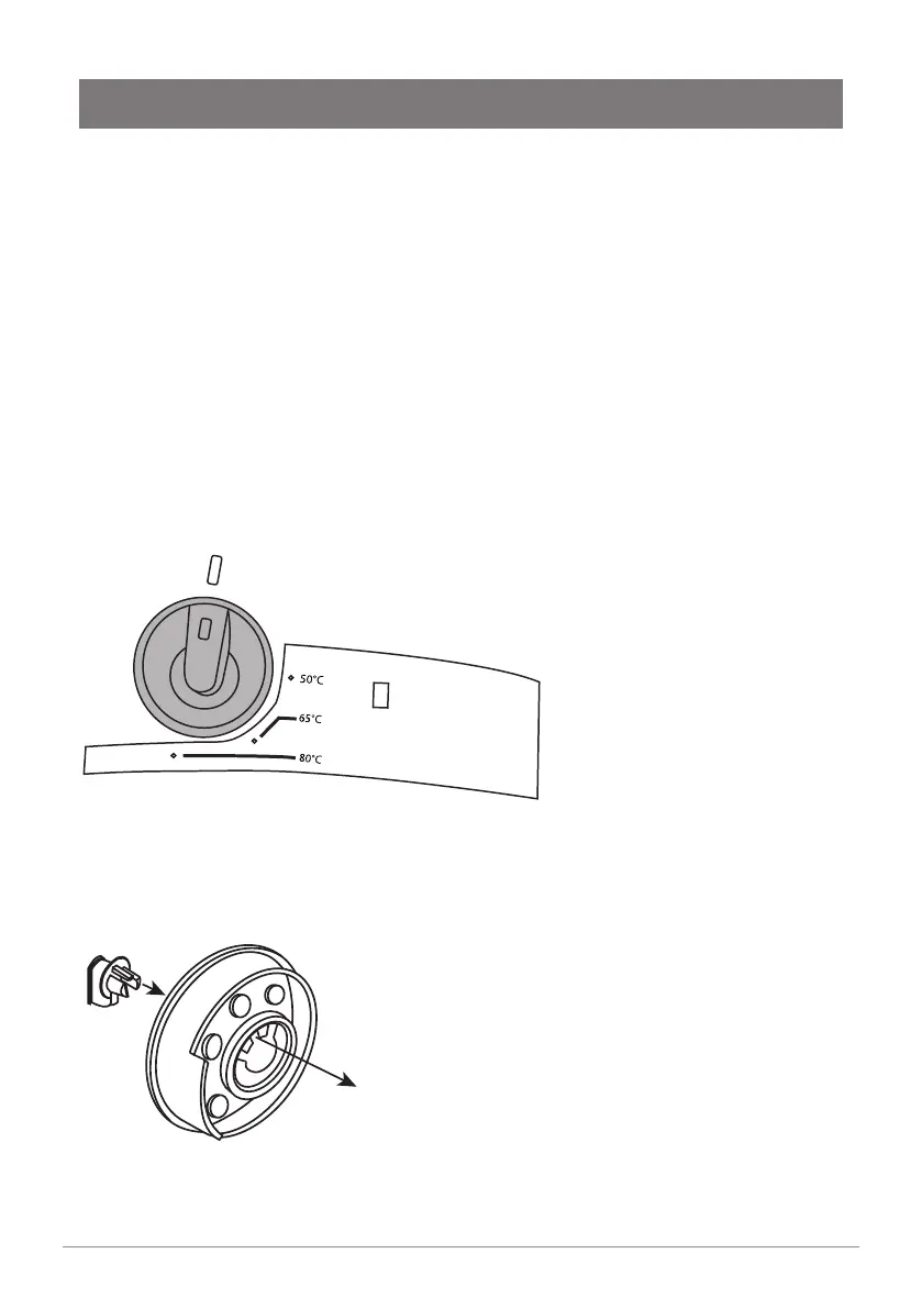
Temperature Limitation
• Turn the temperature selector to the position shown in
Fig.3 and then pull the selector from the spindle.
• Press out the small manual insert from the
inside of the selector and refit in the required maximum
position. ( 50°C, 65°C or 80°C).
• Refit the temperature selector on to the spindle. (The
temperature cannot now be set to a value higher than that
fixed on the selector).
Note The water heater cannot be
switched off via the temperature
selector, it can oly be switched off
at the isolation switched mains
supply socket.
80
65
50
Temperature Limitation
• Turn the temperature selector to the position
shown in g.3 and then pull the selector from the spindle.
• Press out the small manual insert from the inside of the
selector and ret in the required maximum position.
( 50°, 65° or 80°).
• Ret the temperature selector on to the spindle.
(The temperature cannot now be setto a value higher
than that xed on the selector).
 Loading...