Do you have a question about the ZIV 7IRD-A and is the answer not in the manual?
Provides a high-level introduction to the 7IRD terminal equipment and its subsystems.
Details the various protection functions offered by the 7IRD terminal.
Outlines the configurable functions of the control subsystem for bay element management.
Describes extra features like circuit supervision, breaker monitoring, and LED targets.
Guides users in selecting the appropriate 7IRD model based on specific requirements.
Specifies the selectable power supply voltage ranges for the terminal unit.
Presents detailed technical specifications for the protection subsystem's performance.
Provides technical data for the control subsystem, including I/O and measurement capabilities.
Details the technical specifications for various communication interfaces like fiber optics and RS232C.
Outlines insulation test requirements according to IEC standards.
Details electromagnetic compatibility test requirements based on IEC standards.
Specifies environmental conditions for operating and storage of the equipment.
Covers power supply interference and ripple test requirements.
Lists mechanical test standards for vibration and shock resistance.
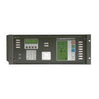
Provides a general overview of the 7IRD terminal's physical structure and components.
Explains the interface and data transfer between protection and control subsystems.
Specifies the physical dimensions and mounting information for the 7IRD IED.
Details the terminal connectors and their arrangement for system integration.
Configures parameters for the protection subsystem, including overcurrent and recloser functions.
Configures parameters for the control subsystem, including communication and general settings.
Explains the operation of overcurrent protection elements in the 7IRD terminal.
Describes the breaker failure detection and backup tripping functionality.
Details the operation of the open phase detection element.
Explains the residual current detection function for unbalance currents.
Covers general operational settings affecting the protection subsystem.
Describes the automatic reclosing sequence and control logic for specific models.
Explains logic functions like trip seal-in and failure time settings.
Details the monitoring of trip and close coil circuits for failures.
Covers functions for monitoring breaker operations like trip counts and kA2 values.
Explains how to manage different sets of protection, logic, and recloser settings.
Describes the event recording mechanism and its data.
Details the information stored in fault reports for post-fault analysis.
Explains the recording and logging of historical metering data.
Details the configuration and function of terminal inputs, outputs, and LEDs.
Covers communication settings, types, and interaction with the unit.
Lists and describes alarm codes displayed by the protection subsystem.
Outlines the general operational capabilities of the control subsystem.
Explains the structure and function of the control unit and its components.
Introduces the device's display and keypad interface for operation.
Explains the functions of various keys and operational modes of the keypad.
Details how to access specific functions like trip indication and recloser status via the F2 key.
Describes methods for accessing various functions and settings via the keypad.
Explains how to access and operate control functions through the keypad interface.
Provides a general overview of the graphic display and its operation.
Explains the device representation symbols used on the graphic display.
Guides users on how to navigate and access information screens via the graphic display.
Details procedures for executing control operations using the graphic display.
Provides general safety precautions and an overview of acceptance tests.
Outlines steps for initial physical examination of the equipment.
Describes isolation test procedures to check electrical harness integrity.
Details the procedure for testing the power supply connections and indicators.
Covers essential reception tests for the protection subsystem's functionality.
Details critical reception tests for the control subsystem's hardware.
Explains how to perform communication tests using the local port.
Provides guidelines for the proper installation location and connection of the unit.
Configures PROCOME 3.0 protocol parameters like passwords and timeouts.
Explains the operation of the PROCOME 3.0 protocol, including event masks and fault reports.
Describes how the keypad and display are used for PROCOME configuration.
Shows the physical layout of the rear ports for DNP 3.0 communication.
Configures DNP 3.0 protocol parameters and metering changes.
Explains the DNP 3.0 protocol's operation, including MTU/RTU addresses and unsolicited reporting.
Details how to configure DNP 3.0 protocol settings via the keypad.
Provides dimensional and drill hole information for mounting the 7IRD unit.
Illustrates the external connection diagrams for different 7IRD models.
| Display Type | TFT LCD |
|---|---|
| Operating System | Linux |
| Communication Interfaces | 2x USB |
| Power Supply | 12V DC |
| Protection Class | IP65 |