Chapter 4. Physical Architecture
M7IRDA2003I
7IRD-A/J/M: Distribution Protection & Control Terminal
© ZIV APLICACIONES Y TECNOLOGÍA, S.L.U. 2020
4-2
4.1 General
Protection Subsystem
Protection Subsystem is supplied with one printed circuit board that provides the following
functions:
- Power Suppl
- Two Trip Outputs
- Processor Module - Two Close Outputs
- Five Analo
Inputs - Seven Auxiliar
Outpu
- Eight Digital Inputs - An Auxiliary Output corresponding to
terminal unit In Service
Additionally, one or two printed circuit boards can be added to provide four contact inputs or
four contact inputs, two trips outputs, eight digital inputs and an output In service.
Control Subsystem
Control Subsystem is supplied with one printed circuit board that provides the following
functions:
- Power Suppl
- Seven Sin
le Contact Di
ital
- Processor Module
- Ei
ht Di
ital Inputs
Outputs (two of them are commutable)
-
n Auxiliar
Output correspondin
to
- Two Double Contact Di
ital Outputs terminal unit In Service
As for the protection subsystem, an additional control printed circuit board can be added.
Depending on the loaded configuration, the available physical inputs and outputs can be fully
used or not.
The measured values used in the control subsystem come either from metering transducers or
from the secondaries of metering transformers. In the second case, measurements are
physically captured and processed in the protection subsystem or in the measurement circuit
board and then sent to the control subsystem via internal bus.
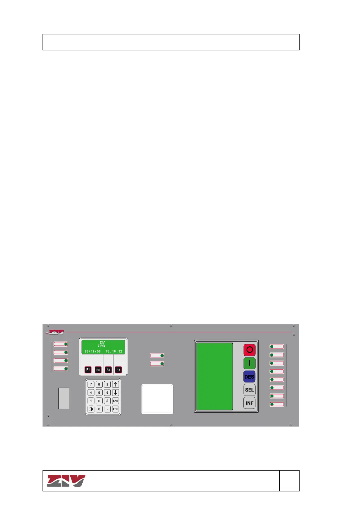
Following figure shown the common front, where there are the alphanumeric and graphic
displays, functional and numerical keyboard, and a local communications port.
Figure 4.1 7IRD Front View.