Chapter 6. Description of Operation of Protection Subsystem
M7IRDA2003I
7IRD-A/J/M: Distribution Protection & Control Terminal
© ZIV APLICACIONES Y TECNOLOGÍA, S.L.U. 2020
6-24
6.8.3 Trip/Close Coil Circuit Supervision Input Programming
The characteristics of the Status Contact Inputs (IN-6, IN-8, IN-5, IN-7) used for Trip and Close
Coil Circuit Supervision functions are different from standard Status Contact Inputs. These
characteristics are determined by the four jumpers located on the protection board and called
J2, J5, J1 and J6. These are associated with the IN-6, IN-8, IN-5 and IN-7 inputs respectively. If
the terminal unit is provided with an additional printed circuit board for the protection subsystem,
the jumpers are placed on the printed circuit board that contains the power supply. To use the
inputs for the supervision functions connect the jumper links in the SUP position.
The Status Contact Inputs associated with the Trip and Close Coil Circuit Supervision
functions are made using the programmable inputs software menu. The programmable inputs
software menu enables the assignment of IN-6, IN-8, IN-5 and IN-7 to SBAIA, SBCIC, SSP-1
and SSP-3 signals respectively. The association made in the preceding figure is:
IN-6SBAIA IN-8SBCIC IN-5SSP-1 IN-7SSP-3
The Trip and Close Coil Circuit Supervision functions operate separately. If only one coil is
monitored, the other Status Contact Inputs can be used for other functions if the printed circuit
board jumper links are modified.
6.8.4 Trip/Close Output Supervision
The Trip and Close Coil Circuit Supervision functions described are also used to monitor the
Auxiliary Contact Outputs used for the trip and close signals:
Trip Coil Circuit Supervision Trip Output Supervision
Close Coil Circuit Supervision Close Output Supervision
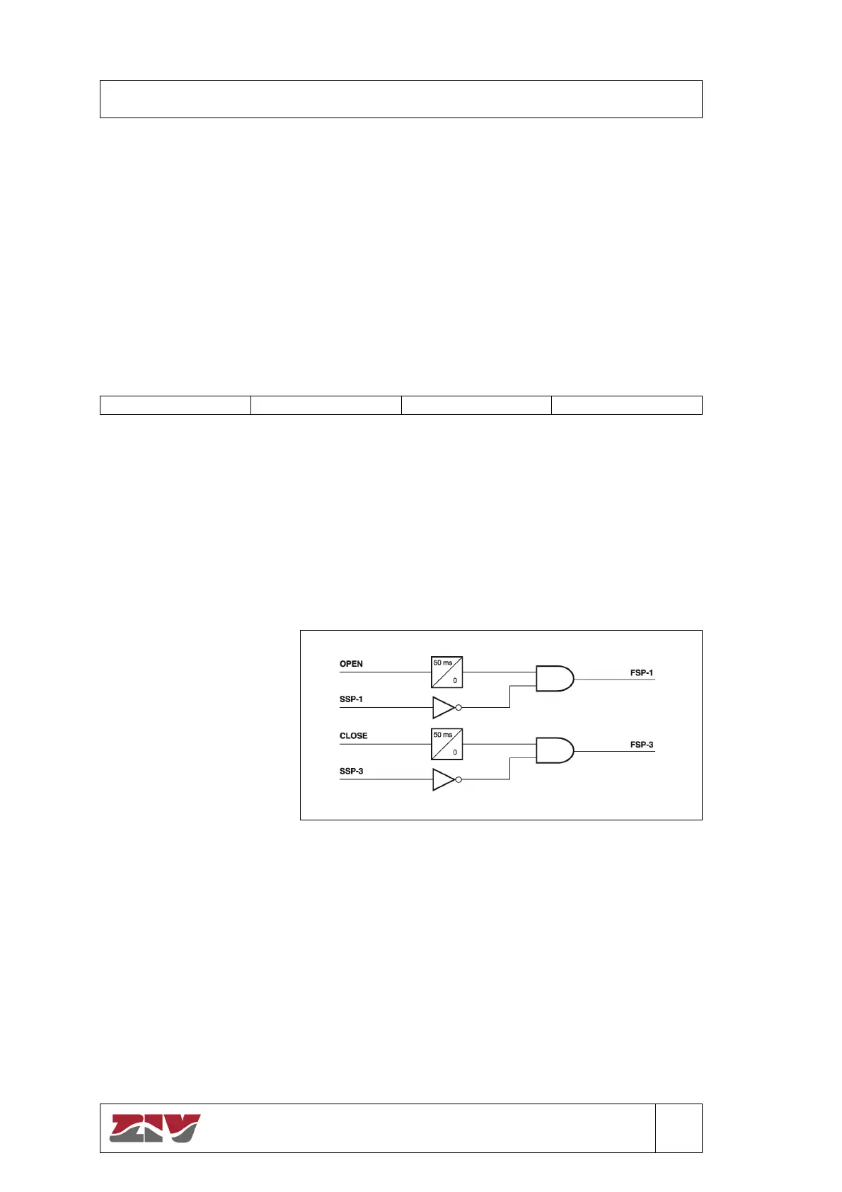
Signal FSP-1 indicates
that the terminal unit trip
output contact failed to
operate properly. This is
determined by monitoring
the logic “trip” command
generated within the
microprocessor and the
status change of input
IN-5 (SSP-1). A 50 msec.
time delay is provided to
allow for pickup of the
tripping contacts.
Figure 6.13 Trip/Close Output Supervision Block Diagram.
The close output is monitored in a similar manner. Signal FSP-3 indicates an improper close
operation.