Chapter 10. Receiving Tests
10-11
M7IRDA2003I
7IRD-A/J/M: Distribution Protection & Control Terminal
© ZIV APLICACIONES Y TECNOLOGÍA, S.L.U. 2020
Measuring the Input Transducers
Apply direct current on the Input Transducer and check that the measurements taken from
Communications or on the Measurements Screen of the display coincide with those of the
following table whenever the constant of the Transducer is in “1”.
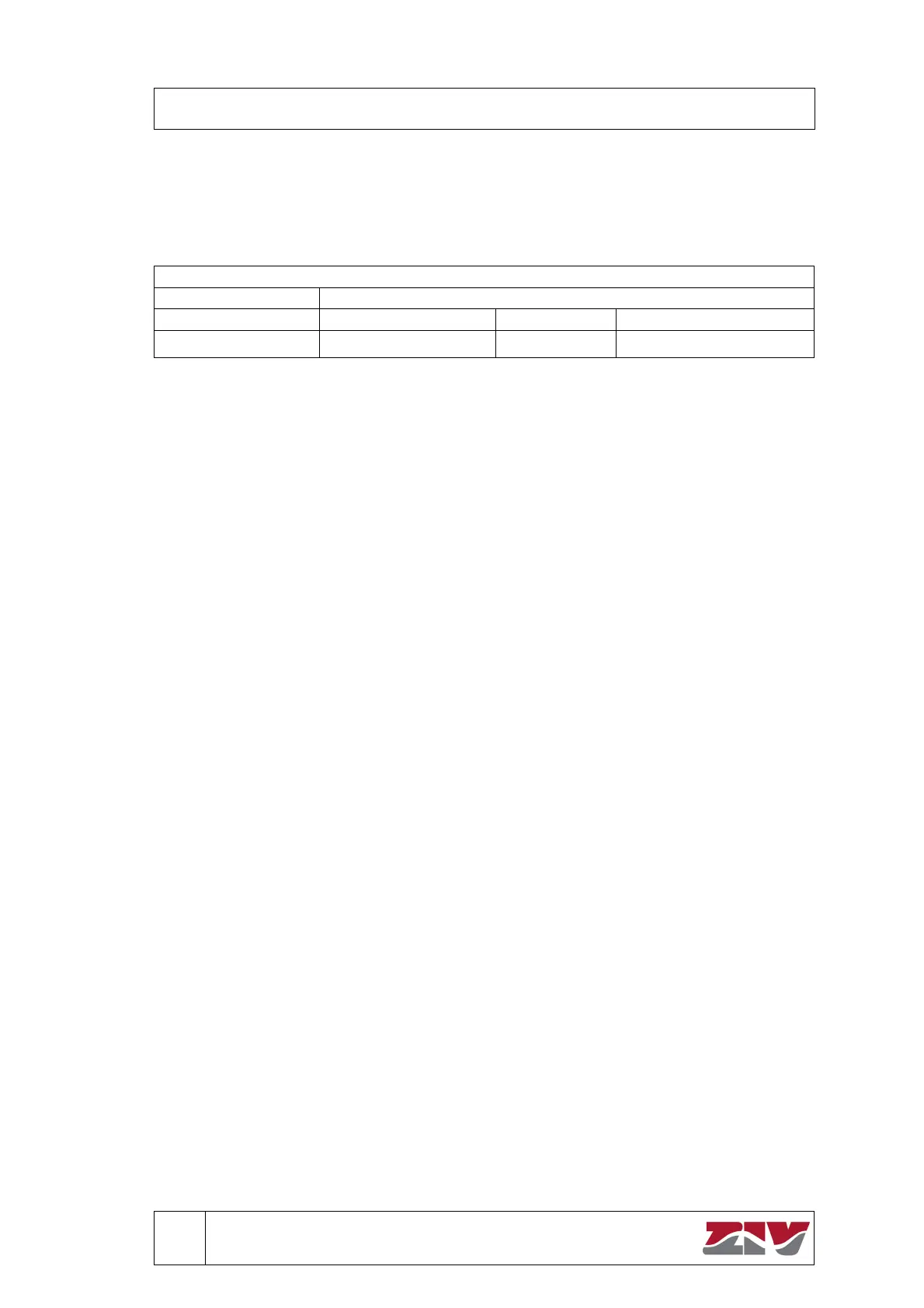
Table 10-6: Measuring the Input Transducers (Control)
Transducers
C Applied (mA) 0 - 5 ± 2.5 ± 1
X
X 0.025 X 0.025 X 0.005
10.7 Communication Test
To carry out the Communication Test, it is necessary to supply the equipment with its rated
voltage value and the In Service LED should then be switched on. Test will be performed
through Local Communications Port, allocated on Front Panel. This port has the fixed settings
that follow:
Baud Rate 4800 Bauds
Stop Bits 1
Parity 1 (even parity)
Connect to the terminal unit through the Local Communications Port using a DB9 (9-pin) serial
connection wire. Synchronize time using the ZiverCom
®
software program. Disconnect the
communications wire and disconnect the terminal unit Power Supply and wait for two minutes.
Afterwards, connect the Power Supply and connect to the terminal unit through the Remote
Communications Port. Activate the “cyclical” mode in the ZiverCom
®
software program and
verify that time actualizes properly.
 Loading...